All Right!
Hi Gregg,
Bigger smile. I am very happy things finally worked out for you.
Now for the fun part. Let's fix this thing. I would like some info on the power supply and, of course, the MPX circuit board. Can you try a pic of the entire MPX PCB in one take? The focus seems to get better when your camera is further out.
-Chris
Hi Chris,
Important note regarding the schematic. The 2 Amp Boards F-1040 (or F-1040-1) have been replaced with F-6013, the Manual explains the installation procedure which involves cutting wires and shorting them to ground. The schematic will not show these changes. This procedure was done on all 3 models (5000, 5000A and 5000X).
When you saw photos that "looked closer," they were actually larger in the Manual. My camera has a fixed focus. I can set it to normal or "macro." When you saw "blurry" photos, I was either too close, too far, or moving. There is only one exact distance where I get a sharp "macro" image. I cannot change the distance; which means I cannot get the schematic in one shot.
I took another series of photos and I will send it to both you and Hugo in PDF format. There are three sets of photos in the file with a "separator" image to show the beginning of each circuit board. Each shoot begins to the left and continues to the right, (and then down).
I shot the power section last and I used a PC photo program to write the letters "A" and "B" (in the color red) with arrows pointing to the two wires that lead back up to the two circuit boards. So, as you begin looking at the photos, you will first see the letter "A", and then later you will see the letter "B." When you get to the last section (the very last photo) you will see which wires A & B actually are, and where they come from.
I promise it will make sense when you see it. I once had an engineer tell me: "For someone who can't read or draw a schematic, you sure have your own way of drawing that makes it make sense."
Let me know if I failed this time.
Ps... Hugo, the 5000, 5000A and 5000X all use the same schematic. They have minor differences in the Manuals with regard to three small circuit boards. The only difference between the new manual and the old manual was two circuit boards. I suspect if the first seller had sent me a schematic, it would have been the same as the one I just got with the 5000A manual.
Sincerely,
Gregg
Hi Gregg,
Okay, some assembly required. Doesn't it figure you just needed the schematic.
Hugo,
it's been too dark for pictures. So I found my scanner (expensive Epson) and tried to hook it up. Guess what? Microsoft strikes again. I have to buy a new scanner because XP (NT & up) will not allow the printer port to be accessed directly. That and Epson has not written a new device driver for it. That would have been better than pictures. Still waiting for sunlight.
-Chris
Now we are getting somewhere!
Hi Gregg,
All right, terminal 4D (MPX board) should have close to 24 VDC on it.
You didn't see that so ... In the power supply, on the 2SC696 collector there should be around +33 VDC as a guess, the emitter will have +24 VDC (about). The base will be around 0.7 VDC more on the cathode of ZD001 (I think). The cathodes on D002, D003 will be around +35 VDC. Also measure on each side of R001, 68 ohm, 3W.
Let me know.
-Chris
Re: Now we are getting somewhere!
Hi Chris,
All readings were about exactly as you listed above. (All readings VDC)
2SC696
Base: 24
Emitter: 23
Collector: 33
ZD001
Cathode: 24
D002, 003
Cathodes: 35
R001
Stereo light wire side: 24
other side: 21
-----------------
Next?
Thanks,
Gregg
--------------------------anatech said:Hi Gregg,
All right, terminal 4D (MPX board) should have close to 24 VDC on it.
You didn't see that so ... In the power supply, on the 2SC696 collector there should be around +33 VDC as a guess, the emitter will have +24 VDC (about). The base will be around 0.7 VDC more on the cathode of ZD001 (I think). The cathodes on D002, D003 will be around +35 VDC. Also measure on each side of R001, 68 ohm, 3W.
Let me know.
-Chris
Hi Chris,
All readings were about exactly as you listed above. (All readings VDC)
2SC696
Base: 24
Emitter: 23
Collector: 33
ZD001
Cathode: 24
D002, 003
Cathodes: 35
R001
Stereo light wire side: 24
other side: 21
-----------------
Next?
Thanks,
Gregg
----------------------------------anatech said:Hi Gregg,
Talk about lucky guesses! How about the MPX board? Terminal 4D. If the 24 V is missing, then trace the wire back. It goes to a switch, but is not switched itself.
-Chris
Hi Chris,
I found something.
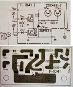
The first power related board you had me look at powers one of the Stereo Light wires. There is another board labeled F-1041 that powers the other wire for the Stereo Light. Both of those Boards are also bringing power to the MPX board (F-1006). The F-1041 board is called the "Protector" in the manual. I tested that board and found the following. (Important: See attached photo).
D901 & D902: Both sides dead
VR901 & VR902: All poles dead
SCR901:
K = Dead
A = 24
G = Dead
Note: Holding probe against G for anywhere from 2 to 20 seconds causes a spark, with a loud pop in the speakers, and then the Stereo light comes on very brightly. I'm not sure if the brightness is correct. It looks too bright to me. However, after the Stereo Light comes on, G then reads 0.7 volts. Also, at the same time all sound goes dead (total silence) *including* AM Radio which was previously working fine. Switching the unit off resets it back to the previous condition of no Stereo Light, and normal volume everywhere but FM Radio.
If you look at the Block Photo, *all* of the components to the RIGHT of SCR901 have current. What I don't understand is that *every* contact point reads 24 VDC, (with the contact points on the other side of the resistors reading 23 VDC). The same is true of the Transistors. The difference between Transistor Base poles is only + or - 1 volt.
Keep in mind that for me to read the 24 volt range my meter must be set to 60, the next step up is 300, so looking at a difference of 1 volt is difficult at a setting of 60, (i.e: 1 volt becomes the midpoint between each line on the dial), and it is impossible to see 1 volt at a setting of 300. And the lower setting of 15 can't be used at 24 volts. (My options are 0.6, 3, 15, 60 & 300).
However, *all* circuits (all contact points) to the LEFT of SCR901 are completely dead.
When the Stereo Light comes on, *all* contact points to the RIGHT of SCR901 (which were previously reading about 24 volts), drop to about 1 volt (+ or - about 0.35, depending on which side of the resistor I test). I can take more exact readings if needed. And *all* contact points to the LEFT of SCR901 are still dead as before.
Note: I tried my best to give you enough information to draw conclusions as to what is going on.
Am I buying SCR901 yet, or is something not right about the readings I am getting from the circuits to the RIGHT of SCR901?
I anxiously await your answer...
Sincerely,
Gregg
Attachments
Hi Gregg,
That is a protection circuit to shut off the amplifier in case of a fault. When you touch the gate, you induce a charge that fires the SCR. It will stay on (in protect mode) until the power is turned off and on again. This circuit kills the 24 V supply which also may provide the tail current for the diff pairs in the amplifier section.
D901, D902 come from a fault detect circuit. Either one going positive will trigger the SCR. I don't know what is sourced by TR901, TR902. They may feed the amplifier section. The current is limited to 90mA or so by the lamp PL001. The voltage at T903 (from the lamp) should be at T904 less about 1.5 ~ 2 volts. If there is no voltage, test for a short to ground (power off) or any of the 2R2 or 10R resistors open. An open B-E on either TR901 or TR902 will do the same thing. I don't know what's going on with the stereo lamp. You should measure the voltage across it when it's on.
SCR901 is fine.
-Chris
------------------------anatech said:Hi Gregg,
That is a protection circuit to shut off the amplifier in case of a fault...
SCR901 is fine.
-Chris
Hi Chris,
I'm stuck. I've been poking around for 8 hours and all I'm doing is poking around. I don't know enough to know where to look or what to look for. It's not a simple matter of "the shin bone's connected to the knee bone," because I don't know which bones are connected where.
If you can't tell me "look at this (specific thing), and check for that (specific voltage)..." I can't do it. I really can't. I'm quite willing, as my entire lost day will attest to. I just don't know what I'm doing.
SCR901 is proof of that. The 6 hours since then nails the lid on my diagnostic coffin.
:-(
Gregg
Hi Gregg,
I have been there as well. You must check the thread manually as it seems to take a while to notify via email some times.
Look on the bright side. Now you know what sparks and what doesn't spark ... And you're still breathing too! Right on.
So let's start anew shall we? What are your readings at 4D on the MPX board and D4 (?) on the power supply pcb (your marking "B")?
This wire runs from the power supply to the function selector switch terminal and continues to the MPX board, also to "E" on the schematic. If you turn the power off and let it sit for ten minutes, thenput one probe to the MPX point and the other on the power supply point on the resistance scale (lowest), you should read a short or very close to it. If you do not, then the wire is either broken or miswired by a previous tech (struck by technician). Or if you'd rather, TIM (technician induced malfunction).
-Chris
--------------------------anatech said:Hi Gregg,
...What are your readings at 4D on the MPX board and D4 (?) on the power supply pcb (your marking "B")?
This wire runs from the power supply to the function selector switch terminal and continues to the MPX board, also to "E" on the schematic. If you turn the power off and let it sit for ten minutes, thenput one probe to the MPX point and the other on the power supply point on the resistance scale (lowest), you should read a short or very close to it. If you do not, then the wire is either broken or miswired by a previous tech (struck by technician). Or if you'd rather, TIM (technician induced malfunction).
-Chris
Hi Chris,
4E = 24
4D = 0.6 (0.7?)
D4 is actually OH (it's probably blurry on the photo). It is what I marked as "B" in red on the photo. It has 24 Volts. There are two wires at OH (D4). One runs directly to 4E on the MPX board, and the other is one of the two wires (orange) that runs directly to the Stereo light (which doesn't light up even though both wires have 24 volts).
I was surprised when that "protection circuit" made the Stereo light work. I (more than) probably just don't understand the circuit. Two 24 volt wires to a 3 terminal socket, one of which is ground. Both wires have 24 volts at all times, but the light only lights when the protection circuit kicks in? (I don't "get it").
You know what. It can't be the "Stereo Light." When it's lit it just shines through a red lens with no wording; and it's located on the extreme right side of the unit, which is the opposite side of where the Tuner indicators are. So, it must be *strictly* a "protection" circuit light. Whatever, but I don't understand how it works.
Anyway, with the power off (and after 10 min), I followed the black wire from 4D on the MPX board to the Selector switch. There is good continuity (an "almost short") between the two connection points (i.e. "the Selector switch and 4D").
I went further and followed the connections on the Selector switch. When the Switch is on "FM", the black wire (that leads to 4D) is connected to two other points on the Selector. One point goes to the MPX Separator Pot. The continuity between those points is good. The second wire goes to a circuit board which is located right next to the selector switch. The continuity at that point is also good. I can check any of those points directly against 4D and I have good continuity (an "almost short").
By the way, what you are referring to as the "power supply" is the board that I thought had a problem the other day. It's the one that I posted a photo of here at the site. It was the photo of a part (ZD001) that was replaced ("cut above the circuit board"). I then posted a "NEVERMIND" when I found that a replacement part acted the same way. You replied that the readings I got were good. (Quote: "What you measured on the diode is normal").
So this means we *really are* back to the beginning!
In short, I seem to have confirmed that everything you questioned is doing what it is supposed to do. What I don't understand is why, (when the power is off), I have continuity between ground and all of the test points on the MPX board; (including 4E where I get 24 volts when the power is on).
I find all of this very confusing. Not understanding the circuit it makes it (more than) difficult to trace the circuit as I go out from the points where you start me off at. It's difficult enough not knowing what voltage to look for, but it becomes a nightmare when there are "shorts" that are *supposed* to be there.
I'm not sure that last paragraph makes sense.
still no smiles,
:-(
Gregg
Hi Gregg,
By chance, is 4D and 4E near each other on the MPX pcb? Do the leads look as if they have been resoldered at some point?
Connection 4D is to be wired direct to the power supply, to OH. Connection 4E goes through a switch contact, 24 V at this point will kill the sound by cutting off TR403. This might actually be a "stereo only" switch. Therefore TR403 only works when TR408 is on (ie stereo is detected).
The stereo lamp is fed from the protection board. In protect, the stereo light goes out. The other lamp is "protect". That is if I am reading these sketchy details correctly.
Swap them and see if it works. (4D and 4E at the MPX board).
-Chris
-------------------------anatech said:Hi Gregg,
By chance, is 4D and 4E near each other on the MPX pcb? Do the leads look as if they have been resoldered at some point?
Connection 4D is to be wired direct to the power supply, to OH. Connection 4E goes through a switch contact, 24 V at this point will kill the sound by cutting off TR403. This might actually be a "stereo only" switch. Therefore TR403 only works when TR408 is on (ie stereo is detected).
The stereo lamp is fed from the protection board. In protect, the stereo light goes out. The other lamp is "protect". That is if I am reading these sketchy details correctly.
Swap them and see if it works. (4D and 4E at the MPX board).
-Chris
Hi Chris,
I've got several pieces of bad news and several pieces of good news.
Bad news:
#1) My Meter died while doing the last procedure. Nothing fried. I think the needle gauge just died. It doesn't do anything on any setting, and the battery is good. (A new battery made no difference). I built that Meter 20 years ago. Bummer.
#2) It was hard to tell if someone changed the wires because the unit has been serviced extensively. There are many obvious repairs, much of which were recall related. The recall procedures involve changing the wiring, and grounding circuits that were previously used in the boards that were replaced. The new manual I bought came with the "How To" procedures listed in detail. And like a lot of Solid State equipment I see, this unit looks very "home made." By that I am referring to resistors and capacitors that are added onto the bottom of the circuit boards in "Point To Point" fashion. This could just as easily been done at the factory. I have seen other units in which major design changes are made. Rather than scrap new equipment, they do these alterations to bring them up to the revised specs. On the other hand, this could also just as easily be a "hack job." I am trying to say it's impossible to tell.
#3) When I tried to remove the two wires from the posts to switch them... I applied heat, and then gently pulled on the wire with needle nose pliers. The entire pin came out and the copper on the circuit board pulled off the board. When removing the second wire, the same thing happened in spite of every precaution I took to prevent it. I managed not to pull the copper completely off the board, but the whole pin still came out. I switched the wires as you suggested and repaired the pulled copper on the circuit board by flowing solder. It was only 1/4 of an inch in distance and there was only one "point to point" involved. In other words, no big deal. No serious damage was done, and it was not a serious repair.
#4) It made no difference whatsoever. Everything worked the same as before.
#5) My wife reached her wit's end with me and this stereo being all over her Dining Room table for two weeks. She didn't "nag" about it, but she became visibly emotionally upset over how long this was taking on her Dining Room table. Between that fact and the "Bad News" items 1 through 4 listed above, time had essentially run out for this project.
Good news:
#1) I unsoldered the two wires to put them back the way they were, and I decided to try an experiment first. I turned the unit on with the two wires *disconnected*. There was dead silence. No hiss, no hum, no nothing.
#2) I had previously commented that other than no sound in FM, the unit worked "perfectly." That isn't exactly true. The unit had a small amount of "hum" when set to other sources such as Tape and Aux. It was very, very, minor. I was told by someone else it was "60Hz hum from old Caps." However, with those two wires disconnected, it was 100% gone! I can now set the unit to Tape or Aux with *total* silence.
#3) Because everything else now *really does* work perfectly (including AM Radio), and since I have a separate FM Tuner, and since my Meter is history, and since my wife has lost all patience with this thing on her table, I decided to tape the two wires, leave them disconnected, put the unit back together, and use it with a separate FM Tuner.
#4) I actually did one better than that. I decided to use my Solid State Preamp since it has source buttons for everything, and it is very simple to operate. It even has a volume control. My wife *needs* "simple." We previously had an IC based receiver that had so many buttons she would lose volume by doing something as simple as accidently pressing the "Tape Monitor" button. (That unit burned up under low output use). I bought this Sansui because I *prefer* the sound of Solid State units. There is something "flat" in the sound output of IC based amps. In fact, I notice the difference *so much* that I wonder if it's because I "grew up" listening to Solid State systems, and just got used to that particular sound? Or do Solid State units *really* produce a better sound? (I'd be very interested in your opinion about that).
So, I set the Sansui to AUX, and connected the preamp outputs into the Sansui's Aux (it doesn't have preamp inputs). I set the volume to 50% and set the Bass and Treble flat. I left out all filters. In other words I am using it as an amplifier. I also left the power "on" and sent it's power wire to the switched outlets on the preamp. So, all my wife has to do is power on the preamp and select which source she wants. She never has to go anywhere near the amp itself. *AND*, if the power goes out in the neighborhood, I don't have to worry about losing the settings. (I *really* like that fact about older systems).
Fortunately, the listening volume at which we listen to music is such that changing the volume on the preamp is enough to control the volume though the speakers at a range that sounds good. (I'm not sure if that statement made sense, but I think you know what I mean). We don't listen "super low" or "super loud."
In the mean time, I will keep my eyes out for a Sansui 5000 that sells dirt cheap. Like maybe a unit that is physically beat up, but working fine. I can then use the parts to fix my unit. I can just do one big massive "transplant" of all working parts.
I would like to thank you (and Hugo) for all of your help. I do not consider it a waste of time because I learned a great deal; (actually "re-learned" what I had forgotten). I will continue to visit this web site because I enjoy it very much.
Ps... Hugo, thank you *VERY MUCH* for scanning and uploading the schematic.
Sincerely,
Gregg
Hi Gregg,
I am glad you seem to have a working system. I admit the dining room table can only be used if you are single! Your wife has much patience. Mine would never allow such a thing. Go buy her something she would like for her great patience. If you don't, you do not deserve her.
It's clear that you need to assemble some basic things. A work space. A modest oscilloscope (a 20MHz one will do, they are reasonably cheap, new), and a half decent digital meter. A used Fluke 45 of HP 34401A is great, a used Fluke handheld (new- ish), or maybe a new Escort or Leader. Most others are just okay. This may take you a year or so to do.
Cruise the forum. I think building an amp would be a good project for you. You might be able to Dick up a dead amp for the case and transformer (+ heatsinks maybe) and build something nice in that.
-Chris
------------------------anatech said:Hi Gregg,
...I admit the dining room table can only be used if you are single! Your wife has much patience. Mine would never allow such a thing. Go buy her something she would like for her great patience. If you don't, you do not deserve her...
-Chris
Hi Chris,
Dig it. She's not into material things, but some flowers for the (now clean) table would go over nicely.
Thanks, buddy.
Sincerely,
Gregg
It has been years since I worked on one of those, but has any of you thought about how the mute circuit in a Sansui 5000 really works?
One version of the Sansui mute circuit in their early transistor receivers used a crude optocoupler: a phototransistor encased with a light bulb. When the light bulb illuminates the phototransistor UNMUTES the tuner. The mute switch on the front panel turns that light bulb on all the time; otherwise it goes on and off according to the signal strength (adjusted by a potentiometer on the tuner board). So when the light bulb goes the way of all light bulbs (and remember, that light bulb is about 25 years old at least), the phototransistor NEVER UNMUTES. So the tuner is in mute all the time.
As near as I can remember, the component looks like a black cylinder with wires coming out of it. As I said, it has been a long time. Many years ago Sansui ran out of those replacement parts (even before Sansui itself crashed and burned and wound up in the hands of the Turks, before being sold to its current owners). I remember that we used to just bypass the muting function to get those sets' FM working again. Sorry I can't help with telling you where that thing is, underneath the chassis. Brain fade with age, you know.
Now, back to the Garrard A70 turntable that's on the kitchen table this afternoon...
----------------------------Netlist said:Very nice tip. If indeed the lamp of the MPL251 is broken, the signal coming in from 2X will not show up on 2Y regardless of the position of S1a. Here's that little nifty diagram.
/Hugo")
Hi Hugo, (and GP49)
This is a very interesting development in that the whole point of my post (besides seeking any help I can get), is my suspicion that the problem has common cause. The reason I have been assuming this is because I keep hearing of this exact same problem affecting many of these units.
That "ebay ad" we discussed has resulted in numerous requests from people asking me for the Sansui 5000 Manual and Schematic, and *every* request has been accompanied by a plea for any information I can offer regarding this very same problem with no sound when using FM. (The best I can do is forward the Manual to these people, and also refer them to this thread).
In fact, the problem is *so* common that a bad light bulb makes perfect sense.
I have been looking at this image of the MPL251 circuit for about an hour and I am once again hobbled by my inability to fully understand a schematic. Can you (or anyone) tell me how to test this circuit, and also explain how to bypass it? If not, then all I've got is a nifty diagram.
For example, you stated "the signal coming in from 2X will not show up on 2Y regardless of the position of S1a." That suggests to me that it is not a matter of running a jumper. It sounds as if a specific measured "something" must be produced by that circuit. Yes? (No?).
I (once again) apologize for my ignorance regarding schematics. It's a problem that "short circuited" a career in electronics 25 years ago.
Thanks,
Gregg
- Status
- This old topic is closed. If you want to reopen this topic, contact a moderator using the "Report Post" button.
- Home
- Amplifiers
- Solid State
- Need help with Sansui 5000