I'm not sure if this is right....
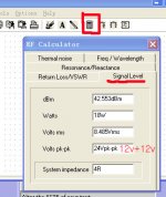
I read somewhere that yo can calculate the output power using a shower resistance plugged into the output and generating a sine wave. Then you measure the output voltage and apply in the formula:
W=V*V/Z
where W is the power in Watts, V is the output voltage and Z the resistance, but I saw another formula that seems more correct but I can't remember.
Please, correct me.
Hi,
the amplifier has two limits for output power.
First, the +-12V limits the peak voltage into the load to about 3 or 4 volts below the supply rail (less the ripple).
The power limit can be calculated from Ppeak=V^2/Rload
Power=V^2/(2*Rload).
The output stage is a single ended ClassA. The peak output current is limited to the set value of the output bias.
The power limit for current is Ppeak=I^2*Rload
Power=I^2*Rload/2
From this last formula you will see that using a lower load value LOWERS the output power limit. The first formula shows that a lower value of load raises the output power limit.
You need to calculate both limits.
As one increases the bias current the heatsink and the output devices run hotter and soon will lower the SOAR to such an extent that the devices will blow up. This is particularly true with low impedance/low sensitivity loads.
If I have +/- 12 V power supply and 4 ohm speaker, what is the output power then? What is the formula?
With +/- 12 Volt Poweer supply, you have a total supply voltage of 2 x 12 = 24 Volts.
Assume that the Voltage loss on EACH output transistor is 1 Volt.
Then the output will swing 24 V - 2 V = 22 Volts.
Hence your 4 Ohm sees a max voltage accross it of 22 Volts Peak To Pek.
Divide Peak To Peak volatge by 2 x root 2 to get the RMS Voltage.
Hence 22 Divide by 2.828 = 7.779 Volts RMS ( i.e. 7.8 Volts RMS)
Power = VRMS x VRMS Divide By R
R = Load = 4 Ohms
Power Output = 7.8 x 7.8 / 4 = 15 Watts.
This assumes that the transistors, and the power supply can deliver... and that the Voltage swing & current from the driver transistors is enough to drive output transistors.
You can ignore one rail.
multiply the measured zero to peak output voltage by 0.707. (one half of peak-to-peak, and easy to see by inspection on a scope) that is the square root of 2.
use that voltage in the Ohms law equation(s).
as someone noted: P = E^2 / R
Best method is to use a real amp on a real load resistor, with a scope that is calibrated or else an RMS meter to get the voltage.
Alternately you can just measure the voltage across the load, and determine the current. That will also tell you the power using Ohm's law.
You may use one rail voltage to approximate the expected power output. In that case the rail voltage is considered to be "peak" voltage, so multiply by 0.707 then plunk that into Ohm's law for power. The real power output will always be lower.
_-_-bear
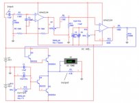
PS. The attached circuit is trying to be a SE class A amplifier??
Why?
Seems like a long way to go for not very much... why not P-P?
And, if ur going to go SE class A, there are better, and easier to build circuits out there... the output in a real world amp needs to be servo controlled or cap coupled to prevent major DC offsets - I presume the last resistor that is being shown measured across is the RL (load - speaker)??
multiply the measured zero to peak output voltage by 0.707. (one half of peak-to-peak, and easy to see by inspection on a scope) that is the square root of 2.
use that voltage in the Ohms law equation(s).
as someone noted: P = E^2 / R
Best method is to use a real amp on a real load resistor, with a scope that is calibrated or else an RMS meter to get the voltage.
Alternately you can just measure the voltage across the load, and determine the current. That will also tell you the power using Ohm's law.
You may use one rail voltage to approximate the expected power output. In that case the rail voltage is considered to be "peak" voltage, so multiply by 0.707 then plunk that into Ohm's law for power. The real power output will always be lower.
_-_-bear
PS. The attached circuit is trying to be a SE class A amplifier??
Why?
Seems like a long way to go for not very much... why not P-P?
And, if ur going to go SE class A, there are better, and easier to build circuits out there... the output in a real world amp needs to be servo controlled or cap coupled to prevent major DC offsets - I presume the last resistor that is being shown measured across is the RL (load - speaker)??
Hi Ampnut,
It would require the bias to be set to at least 2.75A just to deliver that power into 4r0. Since most speakers will draw current that exceeds the 4r0 value, it means that bias will probably need to be set to somewhere between 3A and 4A to get that power prediction into a 4ohm speaker.
The dissipation in the current source and in the output device will now be around 40W each. That is one mighty strong transistor for a 90W device and one heck of a heatsink to stop it blowing up before he even tries to put a signal into the amp.
you know that this condition cannot be met with 1off 2n3055 output transistor running single ended.This assumes that the transistors, and the power supply can deliver... and that the Voltage swing & current from the driver transistors is enough to drive output transistors.
so what is the point in telling him this result?Power Output = 7.8 x 7.8 / 4 = 15 Watts
It would require the bias to be set to at least 2.75A just to deliver that power into 4r0. Since most speakers will draw current that exceeds the 4r0 value, it means that bias will probably need to be set to somewhere between 3A and 4A to get that power prediction into a 4ohm speaker.
The dissipation in the current source and in the output device will now be around 40W each. That is one mighty strong transistor for a 90W device and one heck of a heatsink to stop it blowing up before he even tries to put a signal into the amp.
no.The real power output will always be lower
Measure the Vpp or the Vpk of the output sinewave and use this to calculate the Vac applied to the load. Vac (=Vrms) = Vpk/sqrt(2) =Vpp/{2*Sqrt(2)}
The predicted power from the formula P=Vac^2 / Rload is exact. Not lower.
how do you get almost 3Apeak out of that single ended output stage.+/-11 Volt peak Max Output ...........into 4 Ohm
I don't think any of you are listening!
Even if you use a low power with only 2N3055 and build it yourself I think it’s better than anything on the market.
Bipolar transistors are better than MOS-fet I think, and sounds perhaps better than similar Pass….
Remember that 15 to 20 W is enough for a ordinary listing room for about 25 M2.
I have even used that power, and a Single-end amp on electrostats Quad… and the sound was marvelous so don’t look too much for the power… go for the sound.
")
Bipolar transistors are better than MOS-fet I think, and sounds perhaps better than similar Pass….
Remember that 15 to 20 W is enough for a ordinary listing room for about 25 M2.
I have even used that power, and a Single-end amp on electrostats Quad… and the sound was marvelous so don’t look too much for the power… go for the sound.
Progg70 said:Its water cooled and don’t use 2N3055. I was only interested in
the formula…
Thanks to you all.
Try a single-end and you can’t use anything else… a music lover.
HEY!!!
- Status
- This old topic is closed. If you want to reopen this topic, contact a moderator using the "Report Post" button.
- Home
- Amplifiers
- Solid State
- How calculate the output power