JohnG said:If there is benefit to be gained from throwing away some of the open loop gain of the op-amp, can you throw it away at the output, by a resistive divider, for example? How does this affect the noise of the circuit, compared to throwing away gain at the input?
John
Suppose you want to throw away open loop gain be having the opamp amplify more then required. You would get too much output signal than required.
If you attenuate the input signal, the disadvantage is that the signal-to-noise ratio (SNR) deteriorates: the amount of opamp noise in the output signal increases with respect to the signal. The advantage is improved overload margin because you attenuate the input signal, which may or may not be of some value.
If you attenuate the output signal, you also attenuate the opamp noise, so the SNR is preserved. The disadvantage mentioned by Nelson isn't really there, because if you would *not* throw away gain you would have the same output signal as when increasing gain and then attenuating at the output.
As discussed above, throwing open loop gain away by manipulating the open loop gain directly also worsens the SNR.
So, IMO, if you *have* to do it, I would favor output signal attenuation.
But it is smarter not to get in this situation by chosing a better (for the purpose) opamp.
Jan Didden
Something about opamp's and capacitive load, noise gain and other things....
http://www.analog.com/library/analogDialogue/archives/35-02/avoiding/index.html
The one above was wrong but still helpfull :
Try this one :
http://www.analog.com/library/analogDialogue/archives/31-2/appleng.html
http://www.analog.com/library/analogDialogue/archives/35-02/avoiding/index.html
The one above was wrong but still helpfull :
Try this one :
http://www.analog.com/library/analogDialogue/archives/31-2/appleng.html
We are not talking about throwing away input signal here,
but open loop gain.
If you attenuate the output of a typical op amp by
20 dB, it will only swing about 1 v rms. This is probably
not going to satisfy most users.
There are very few applications where the noise figure
of a state-of-the-art op amp can't afford to be degraded
a bit in exchange for better sound.
Realistically, this sort of thing is only an issue when the
gain of the op amp is set at less than 10 (20 db), usually
in line level stages and followers and the like. Under these
low gain conditions, the noise of the input stage of the
op amp is an infinitesimal. Imagine a 1 nanovolt/square-root-
Hertz degraded to 10 nanovolts. You still won't hear it, but
there's a good chance that the stability difference will be
quite audible.
The second link that Sonnya posted is quite good, and I feel that it makes many excellent points and maps out the general direction admirably, but still doesn't explain the entire story.
In the end, you will personally have to build your circuit of interest, and listen to it with varying amounts of global feedback. There will be a point that you can go up to without problem, above that you will encounter an area where the precise value is a matter of personal preference, and then you will likely hit a region where most listeners agree that the sound has taken a turn for the worse. And this is all with adequate phase margins (with capacitive loading applied).
My findings are that the optimal amount of global NFB depends on the physical structure of the circuit as well as the topology and component choice. And that is why I suggest that you do the experimentation for yourself, rather than asking someone else.
I will add that _how_ you deal with the excess gain will also affect the sonic outcome.
regards, jonathan carr
I seem to be shooting myself in the foot recently, all in the name of brevity and/or haste.
Something I was going to say in my last post, but left out, was that you can remove noise at pretty much any point in the amplification chain that you choose...at a price.
Either analog or digital methods are available. Filtering, dynamic gating, statistical analysis for patterns in the signal, you name it. The price is that you're getting into some serious complexity; the noise-removal part of the circuit can easily have ten times the parts count of the circuit itself. Commercial examples were all the rage for a while: the Phase Linear Auto-Correlator (dynamic gating) and the Burwen TNE-700/A (triggered off signal rise times) come to mind. I seem to recall seeing the schematic for the Burwen unit. Ugh. <i>Not</i> minimalist.
All strategies I'm aware of work best if you're willing to accept decreased bandwidth, or are able to work with an uncomplicated/predicable signal--characteristics that don't generally apply to music...
waitaminnit! Sounds like just the ticket for the boom-boom car stereo guys...
Grey
Dorkus originally asked how does the sound of inverted versus non-inverted op amps compare. The thread has covered various ground, but I've not read any comments regarding listening tests per se. When Thorsten was asked this question on the Amp Chips DIY forum, he said he no longer listens to solid state and that his comparisons of inverted vs non-inverted came from basically a decade ago. Certainly opamps have improved in that time period.
Therefore, to re-address Dorkus' question: has anyone, for example, used an AD8610 in a circuit and actually listened and compared inverted vs non-inverted topologies?
One thing intriguing about this particular chip is that the spec sheets indicate its slew rate is the same at unity gain both in inverted and non-inverted mode (unlike the AD627, where the AD627 has a markedly slower slew rate in the non-inverted mode).
Robert
jcarr said:My findings are that the optimal amount of global NFB depends on the physical structure of the circuit as well as the topology and component choice. And that is why I suggest that you do the experimentation for yourself, rather than asking someone else.
A very apt statement. Everything matters. The idea behind this statement applies to almost anything hifi.
I had a good laugh today reading a letter to the editor of Audio Critic magazine. I paraphrase: "could you do more speaker reviews, the only components that actually sound different..."
dave
Actually, he might have not been too far from the mags philosophy.
Here's a quote from a review of a QSC Audio pro audio amp in the same issue #28 :
"Regular readers of The Audio Critic know that we don't go into the specifics about the sound of a well-designed amplifier, since it is the same as that of any other well designed amplifier...."
-Peter Aczel
At the end, the techical reviewer in the sidebar is forced to say:
"Good for sound reinforcement applications, but ultimately other choices are better for consumer aplications" He can't say WHY , because there are no differences....
Of course the out is saying "well-designed" but in fact the only knock Mr. Aczel has on the amp is the noisy fan..
I picked it up on the news stand. Probably will be awhile before it do it again.....
If we were all to do the experimenting by ourselves and not ask anyone else for their opinions, then why are we reading and writing any of this nonsense? While all the magazines may have jaded reviews for one reason or another, here the only Aczel to grind might be our pride in our work.
Granted we all have different hearing capabilities (and obviously different grammatical skills), different listening rooms, different emotions, and, egad, different--but according to Aczel, the same-- sounding electronics. I would hope the point of this forum is that by sharing experiences, and despite all these differences, we could perhaps learn from the opinions of other (aside from Aczel) and maybe, just possibly, enjoy ourselves and have fun.
I like hearing what others think their electronics sound like; maybe it'll encourage me to try something different.
Regards, Robert
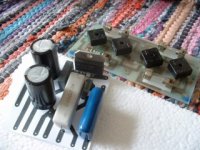
I am currently building LM3875 gainclones in both inverting and non inverting variants, and I will also try skinning the capacitors.
Below is a piccy of an unoptimised layout for an inverting version, and a completed rectifier board.
Further details will follow...")
Below is a piccy of an unoptimised layout for an inverting version, and a completed rectifier board.
Further details will follow...
Attachments
Nelson Pass said:
[snip]
If you attenuate the output of a typical op amp by
20 dB, it will only swing about 1 v rms. This is probably
not going to satisfy most users.
[snip]
Nelson,
Thanks for pointing that out. I had overseen that.
[janneman can be seen repeatedly banging his head to the wall. background sound of weeping violins]
Jan Didden
Al
You should do well to read the gainclone board and the original Lab47 site or else you may end up with a very conventional amp. First, you don't really need a PCB and you'll probably go against the spirit of short signal path if you use one. Secondly, these bridges look very uninspiring, do not doubt that the sound will follow suit. Unless you use first rate components your gainclone will sound like an Elector project.
2c
peter
Yes Peter I know, this is just the first stage, Schottkys, etc, will go in once I have proved to myself I can do it .
The pcb has very short traces for the signal path, as small as if I were to connect components directly to the chip, and the feedback resistor is mounted directly onto the pins of the LM3875, as per the Lab 47 design.
The pcb has very short traces for the signal path, as small as if I were to connect components directly to the chip, and the feedback resistor is mounted directly onto the pins of the LM3875, as per the Lab 47 design.
Robert:
>If we were all to do the experimenting by ourselves and not ask anyone else for their opinions, then why are we reading and writing any of this nonsense?<
As a general rule, this website provide so many guidelines as well as more specific information that IMHO you are very far from having to do "all" of the experimentation yourself.
Speaking from my trial-and-error hands-on experience, the specific implementation matters a great deal when it comes to feedback, phase compensation, and many other matters. Different board layouts have distinctive patterns of stray capacitance and inductance, and some components have far less inductance than others. If you were to measure the inductances, capacitances and leakages of the circuit that you actually built and add those to your schematic, the differences would be pretty obvious, even on the simulator.
My general observations are that some stray capacitance is not always a bad thing - in fact you can utilize it as a natural stabilizing element in lieu of phase compensation networks. However, inductance seldom yields benefits.
Even opamp circuits can behave quite differently, depending on how the power bypasses are done, or whether you use guard rings or not. And sometimes a circuit will have a latent problem that doesn't manifest itself until it gets hit with RF in the problematic frequency band. As you probably know, RF conditions change dramatically depending on the neightborhood. If the circuit was originally designed and built in a locale that had little RF, but was subsequently utilized in an area that had high RF levels, the circuit may not even work correctly. I've witnessed this happen at the CES.
And the above doesn't begin to take other critical factors into account, like personal preference, partnering equipment, or room acoustics.
Nothing is wrong with asking others' opinions, but if you want to wring the best possible performance and sound out of your circuits, I think that you have no alternative to experimenting on your own.
regards, jonathan carr
wow
for some reason i stopped receiving email notices about this thread and didn't know there was discussion still going on...
nice points everyone, thanks for the info. i'm still curious to see if i can pull off inverting mode on the LM1875, and if so how it'll sound compared to non-inverting mode. i'll just have to give it a try. incidentally, the circuit will probably be configured for at least 30dB of gain (need to make up for some lost gain on the shunt attenuator), so i think stability will probably be ok.
What about discrete designs?
Sorry for reviving an old thread, but I have been thinking about
this for a while and finally had some time to go through the
thread again.
Although there seem to be somewhat differing opinions on the
cause of increased distorsion in non-inverting mode, it seems
in all cases to be related to the use of differential inputs in
non-inverting mode. An interesting and obvious follow-up
question would then be whether this phenomenon is restricted
to opamps? It seems to me we should have the same problem
with discrete designs using a differential inputs, shouldn't we?
- Status
- This old topic is closed. If you want to reopen this topic, contact a moderator using the "Report Post" button.
- Home
- Amplifiers
- Solid State
- opamp inverting input sounds better?