Allright i think iv'e almost finished drawing on my amplifier after reading Audio Power Amplifier Design Handbook (D. Self)
Most of it is quite conventional so it's nothing special really but still
I added an current overload protection which enters around something like 5.5A output
Im hoping to take out something like 50-80W from this little beast but please tell me if im a bit too positive")
Please comment anything on this scheme, if any values look strange or so. I'm a little bit unsure of the power-rating for the 10R output resistor, shouldn't have to be greater than a couple of watts?
Ok here's the circuit:
http://upl.silentwhisper.net/uplfolders/upload5/ampproj.GIF
Thanks to you
Most of it is quite conventional so it's nothing special really but still
I added an current overload protection which enters around something like 5.5A output
Im hoping to take out something like 50-80W from this little beast but please tell me if im a bit too positive
Please comment anything on this scheme, if any values look strange or so. I'm a little bit unsure of the power-rating for the 10R output resistor, shouldn't have to be greater than a couple of watts?
Ok here's the circuit:
http://upl.silentwhisper.net/uplfolders/upload5/ampproj.GIF
Thanks to you
Hi !
Looks fine to me, have you verified stability in sims ?
I can't see any problems at once, except you might consider an inputfilter ?
That would be a ~1k resistor in series with the inputcap and a ~330pf
in paralell with the 10k.
This would protect the amp from incoming RF and add some extra stability.
You are biasing the bc556 in the ccs for LTP with ~4.5ma, you should
check if it does not get too hot.
The mje340/350 in vas are biased with ~12ma, that gives 0.4watts,
you might consider some minor heatsinks for them. (try out !)
I would expect ~50watts into 8ohms.
On the other hand, just go and build it, learning by doing !
Mike
"Most of it is quite conventional so it's nothing special really but still"
Ohhhh... you are very wrong! It is special... it is your first amp design and you should be proud for that, because for a first design it is more than good. Congratulations!
"... 50-80W from this little beast but please tell me if im a bit too positive"
Maybe just a little bit less then 50W, if you are planning to use 8 ohms load. +/-36V would be much more on the safe side for firm and "healthy" 50W.
"Please comment anything on this scheme, if any values look strange or so. I'm a little bit unsure of the power-rating for the 10R output resistor, shouldn't have to be greater than a couple of watts?"
I will suggest 3-5uH for inductor and not more than 3,3 ohms 1-2W in parallel.
Of course, that's just my point of view!
Negative pole of the 1000uF and bottom wire of the input 10k resistor and CCS 5k6 resistor should go together on the so called "quiet" or "signal" ground which is separate from "power" or "noisy" ground. Put about 10-47 ohms between those two grounds.
Hi thank you for your replies!!
I've simulated it in Multisim and it acually works pretty fine!
Yes the Vas ccs and vas might get a little warm and if im thinking of putting a small piece of metal to them.
And grounding the input signal, feedback ground and ccs through a 10R to main ground sounds like a good idea. Douglas Self talks about the importance of not mixing "Psu" ground and signal ground together.
I had in mind to take a bit of metal to put the to the two reservoirs together with and put all main grounds there and draw a small piece of metal out of it and use like signal starpoint ground.
Maybe i could take a 10R from the centre of reservoir caps and use as starpoint for all signal earths (including preamp) ?
Anyway here's an update of the scheme:
-added an input filter
- decreased input pair ccs to something like 3mA instead of 4.5mA. I don't think it will make a much different in sound/thd but the transistors will get less hot (thanks for pointing this out) 4.5mA input current is actually quite large
here you go
http://upl.silentwhisper.net/uplfolders/upload2/ampprojscheme.GIF
Hi!
Nice schematic! The 10 ohms / 5W is more than enough. This R-C is used for stability, normally therev is almost NO voltage across the resistor. I use 1W here with no problems. Unless you have oscillations, but this R-C is there to prevent it.
You should be carefull with that 5.5amps current limit. I don't think the output transistors can support 5.5 amps for all output signal levels and real speaker loads. For instance, if you have a reactive load like a speaker with a xover filter, the output may need to supply 4 amps at a Vce across the output transistor of 50V. You would think that this 200W would be safe for the output transistor, but that is not true. The max Ic for a bipolar transistor falls dramatically at Vce above a few 10-s of volts, see the data sheet graph for Safe Operating Area. At Vce of 50V, Ic max is probably (I haven't checked, this is an educated guess) not more than 2 amps or so. I'm sure D Self has a lot to say on this and offers even current limiting circuits that limit current depending on Vce that are really safe!
Jan Didden
Hi Fritzell,
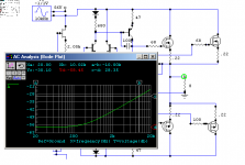
While you have it in sim, you may care to check how much you will be listening to the power supply - by inserting a sig gen alternately in series with the supplies and taking a bode plot (magnitude in dB). This will show you the strength/weakness of your LED current source,miller lagged driver, and overall topology.
See attached a diff'l input with Vas and EF output with very little comp taken on the Vas side.
Cheers,
Greg
Attachments
Hi thanks for your input!
janneman:
Thanks,
I decreased resistor to 3.3R/2W from suggestion from boraomega. Also i agree that the current limiter can be made much better and Douglas Self presents a limiter that also takes the Vce into account but it tended to be a little bit more complicated. And looking in the datasheets for MJ15003/2 their SOA for 5A is Vce~50V (250W) and in this circuit there can never be more that 33V Vce. But as you said with inductive loads things get more complicated...
But i don't think i will ever go so far, i only think that it is good to protect the expensive output transistors. 5.5A limiting is more better than no limiting at all if you by accident short the output
But just to be a little more safe I'll put a 1k-1k divider instead for the current limiters.
amplifierguru:
Good point, i'll try check that. I know Led current source is not as good as the "feedback current source" with two transistors, but it looks cool with an onboard Led Maybe it's better to put the "feedback current source" to the input pair which is more sensitive and a Led for the Vas?
/Fritzell
janneman:
Thanks,
I decreased resistor to 3.3R/2W from suggestion from boraomega. Also i agree that the current limiter can be made much better and Douglas Self presents a limiter that also takes the Vce into account but it tended to be a little bit more complicated. And looking in the datasheets for MJ15003/2 their SOA for 5A is Vce~50V (250W) and in this circuit there can never be more that 33V Vce. But as you said with inductive loads things get more complicated...
But i don't think i will ever go so far, i only think that it is good to protect the expensive output transistors. 5.5A limiting is more better than no limiting at all if you by accident short the output
But just to be a little more safe I'll put a 1k-1k divider instead for the current limiters.
amplifierguru:
Good point, i'll try check that. I know Led current source is not as good as the "feedback current source" with two transistors, but it looks cool with an onboard Led
Maybe it's better to put the "feedback current source" to the input pair which is more sensitive and a Led for the Vas?/Fritzell
Now with PCB
Hi i'm back with a PCB for my amplifier now
Here it is:
http://files.upl.silentwhisper.net/upload1/amplfifierpcb.GIF
The thing in the middle is a small heatsink for the drivers, and output transistors are mounted off-board
Updated schematic:
http://files.upl.silentwhisper.net/upload1/ampschematicnew.GIF
Please comment if i could do something to make it better.
Thanks
Fritzell wrote:
> And looking in the datasheets for MJ15003/2 their SOA for 5A is
> Vce~50V (250W) and in this circuit there can never be more that
> 33V Vce. But as you said with inductive loads things get more
> complicated...
If you drive the output close to the negative rail, the upper
transistor (15003) will see a Vce of 66V minus 2 Re drops
minus Vce sat of the lower transistor (15004) which could be
more than 63 V, or am I missing something?
btw is it 15003/2 as in the text above or 15003/4 as in the
schematic?
best regards,
Gerhard
(my first post on diyAudio!)
Hi gerhard!
It is true that the upper transistor can get 63V of Vce, but when the signal goes under 0V the lower transistor will take over and just the bias current will flow through the upper so the power dissipation can never get higher than ~33Vce * I (or am i totally lost here?? )
It should me MJ15003/4 and not 2/3, must have written a little wrong there. Anyway thanks for your reply
It is true that the upper transistor can get 63V of Vce, but when the signal goes under 0V the lower transistor will take over and just the bias current will flow through the upper so the power dissipation can never get higher than ~33Vce * I (or am i totally lost here??
)It should me MJ15003/4 and not 2/3, must have written a little wrong there. Anyway thanks for your reply
Fritzell said:Hi gerhard!
It is true that the upper transistor can get 63V of Vce, but when the signal goes under 0V the lower transistor will take over and just the bias current will flow through the upper so the power dissipation can never get higher than ~33Vce * I (or am i totally lost here??
Think reactive load here - the direction of current and voltage drop on the laod do not necessairly have to be the same!
Dear Fritzell,
A few comments, if you don't mind:
Let's place 100nF or 220nF foil (MKT) caps near the 220uF elkos on the rails.
The 10R resistor in the Zobel-circut shouldn't be 5W rated. 1W or 2W is abundant. I used 0,25-0,6W rated small resistors in this place, in a 200W/4ohm design, and problem never reported (this resistor disspipating a few mW-s). Anyway if the amp is oscillating (that's a bad fact), then the resistor in the Zobel will be hot, and a small 0,25-0,6W resistor maybe burning out from the PCB, so the best choice is a 10R-2W resistor in this place.
1000uF in the feedback circut is too big, let's use a 220uF cap instead.
The resistors in the emmiters of the LTP-transistors need to be R=26/I (I in mA, R in ohms). In your circut the current is 1,5-2mA per lag, so let's use 13-17ohm resistors here. 15ohm will be excellent.
Input "filters" freq need to be lower then the NFB's freq. So if you using 220uF in the NFB circut, the input cap need to be 4,7u. If you using 1000uF in the feedback (I don't suggested that), then the input cap can be even 22uF.
IMHO it's better to use two signal diodes (1N4148) instead the LED in the CCS. I know, some of good audio engineers (Rod Elliott, ...) suggests LED... But I prefer two 1N4148 in this place.
It's better to use 100ohm resistors instead 39ohm in as linarizing resistors in the current mirror.
The paralel LR circut in serial with the output causes more problem, then good thing. Don't use it.
Diodes in the protection circut need to be fast types (it's very important). Let's use 1N4148s.
The 1k base resistors in the protection circut aren't good wired. They need to be going to the earth with diodes (1N4148s), as shown here: http://sziget.mine.nu/~danko/kapcsrajzok/100w.html
The 1,2k resistors going from the emmiter resistors to the transistors base's is too big: they need to be 100ohm. A 2,2nF foil cap paraleled with this 100ohm resistor will make the protection faster.
I would using 47-470nF foil cap instead the 47uF elko paralel with the Vbe.
15mA current for the VAS is too much. 5mA (120ohm instead 47ohm) will be absolutely enough. The 24k in this CCS is too big, llet's use 10k resistor.
I would using BD139 ad VAS transistor instead of MJE340. BD139 is lot-lot faster.
For driver transistors you should using MJE15030/MJE15031 or BD241C/BD242C devices, especially if you driving a speaker with impedance lower then 8ohm.
All the best, good luck
edl said:IMHO it's better to use two signal diodes (1N4148) instead the LED in the CCS. I know, some of good audio engineers (Rod Elliott, ...) suggests LED... But I prefer two 1N4148 in this place.
It's better to use 100ohm resistors instead 39ohm in as linarizing resistors in the current mirror.
someone here did measure noise on LEDs, zener and diodes and concluded (if my memory is correct that the LEDs (except the blue oens) actually have lower noise than diodes which have lower noise than zeners.
I like to use LEDs as they also serve as indicators that the circuit is powered on.
Yeah, dear tlf9999, you are right, a LED in this place produces lower noise, then the silicon signal diodes.
The only reason thet I using diodes, that I always did it, and I have more 1N4148s than LEDs
Anyway I don't think, that a LED in this place raises the measurable and hearable quality of the whole amplfier. Maybe the noise of the whole amp will goes lower with a few dBs.
So dear Fritzell, let's use LED in the CCS of the LTP as you drew in your schema.
Regards,
Hello Edl,
Made some changes:
- 15R emitter resistors for LTP, 100R for current mirror.
- 4.7uF input cap/220uF NFB cap (I suppose you know what you're talking about)
- Decreased vas current just slightly. Mje350/340 devices don't have so much gain in higher currents so i think 5mA will be almost to little.
- In Douglas Selfs Blameless amp he uses 47uF electrolyt parallell with Vbe multiplier, why is a smaller non electrolytic better? It feels better with a non-electrolytic so i changed it anyway temporarily
- Bd139 for vas
- 1N4148 instead of 4001
- Added 100nF parallell with 220uF on each rail. I've heard people say these can cause oscillation. I don't know if its true but if they cause trouble they can be removed.
- Decreased overload protection resistors to 100R instead of 1k. Else i think this topology works just fine and it's alot better than nothing so i think im keeping it just for the simplicity.
- Output inductors keep the amp more stable into capacitive loads and Douglas Self also uses it in his Blameless amp so i think im keeping that too, unless you don't have any major argumenst why i shouldn't
The reason im using 5W damping resistor is because i found one in my shelf (I think it actually was 9W ) so i don't have to buy one. Same thing with zobel resistor.
Anyway thank you very very much for your comments!
Made some changes:
- 15R emitter resistors for LTP, 100R for current mirror.
- 4.7uF input cap/220uF NFB cap (I suppose you know what you're talking about
)- Decreased vas current just slightly. Mje350/340 devices don't have so much gain in higher currents so i think 5mA will be almost to little.
- In Douglas Selfs Blameless amp he uses 47uF electrolyt parallell with Vbe multiplier, why is a smaller non electrolytic better? It feels better with a non-electrolytic so i changed it anyway temporarily
- Bd139 for vas
- 1N4148 instead of 4001
- Added 100nF parallell with 220uF on each rail. I've heard people say these can cause oscillation. I don't know if its true but if they cause trouble they can be removed.
- Decreased overload protection resistors to 100R instead of 1k. Else i think this topology works just fine and it's alot better than nothing so i think im keeping it just for the simplicity.
- Output inductors keep the amp more stable into capacitive loads and Douglas Self also uses it in his Blameless amp so i think im keeping that too, unless you don't have any major argumenst why i shouldn't
The reason im using 5W damping resistor is because i found one in my shelf (I think it actually was 9W
) so i don't have to buy one. Same thing with zobel resistor.Anyway thank you very very much for your comments!
Dear Fritzell!
+/-33V rails gives you about 70W-RMS power on 4ohm.
The maximal peak output current will be 7,2A (because the impedance of the spaker goes down to 3,2ohm).
Let's say, that the gain of the driver and the output transistors is 60*40=2400. Of course, the real gain is much better, but let's calculate with the worst case.
So the VAS needs 7,2/2500=3mA. Then the CCS of the VAS needs to going on the double of this current (then the VAS transistor can doing the things faster, as a class A amp). So the CCS needs to work at 6mA. So let's use a 100ohm resistor instead the 47ohm as the emmiter resistor of MJE350.
About rail decoupling caps: when the solid state amps appeared, the desingners suggested to use a 100n-220n foil cap as rail decopuler. After, when the power of the SS amps went higher, because the voltage drop on the DC supply cables that caused by the increased peak currents, people started to use elkos paralel with the foil cap, between 10uF and 1000uF.
So the best way is to use let's say: a 100nF foil and a 100uF elko as rail decoupler.
If the foil cap causes oscillations, then there is something wrong with that design. Anyway one of the purpouse of this cap to increase stability... Yeah, and an other fact: the foil cap decrease the bad effect of the elko.
About the protection circut: the solution in your schema limits the peak current, and because this it causing distortions at higher output signals. I don't suggest to use that solution.
I suggest to add two more fast diodes (1N4148, as you can see on the schema linked by me), and this way the circut becomes a short circut protector, and won't cause any distortions. In the HIFI and PA amps I have bulit I always used this solution (2 transistors, 4 diodes, 4 resistors, and sometimes 2 caps to make the protection faster), and problem never reported. Neither with distortion, neither with unsatisfactory protection.
Otput inductor. In the stone age of amps everybody added the paralel RL circut on the output. But than many of the designer found (for example Rod Elliott, and me too...), that this inductor not really improve stability, but it has bad effects: for example it causing distortions (!), or at high output signal this serial inductor make the load that seen by the amplifier more complex.
Me and my designer and DIY-er friends have never used circut (except when the amp drives a 100V line transformer), and problem never reported. But using of Zobel-circut is very-very important! I using 100nF foil cap and a 10ohm resistor in this place.
I know, some of the audio engineers (for example D. Self) prefers the usage of the inductor...
So let's rule yourself!
If you using high watted resistors in the output RC and LC circut (beacuse you have some of them) will make the PCB unnecessary big. A 10ohm-2W (or even only 0,25-0,6W, as I wrote) is dirty cheap, let's buy some of them, when you will go to the electronic trader to buy the things for your amp design.
Best Regards, respects from Hungary
hi ! Why ? I think using a lower degeneration reisistor will need a bigger compensate capacitor .The resistors in the emmiters of the LTP-transistors need to be R=26/I (I in mA, R in ohms).
will gm increase if current through LTP increase ?
I only aquainted with h models . If I'm right . Biasing a higher current through LTP will need a lower degen resistor (?) . But with a higher gm will increase gain of amp and amp will occsilate easylier
I haven't ever try to use a ccs with LED . I used ccs with 2 1n4007 and with 15 V zener . 15 v zener give less noiser than 2 1n4007
about output choke , some one say that we only need it if it is neccesary
Hi Thanh,
A 2BJT current source will give lower noise than any diodic reference. Yes the Re's (degen at 26/Ie) will decrease as Ic increases, proportionally. Choosing them at this value doubles the diff'l signal handling at the input from 52mV to 104mV and improves the linearity. loop compensation C should not change - except if there is different forward gain/phase due to changed GBW of the stage at different Ic.
Cheers,
Greg
and this way the circut becomes a short circut protector, and won't cause any distortions.
I know the simple version causes distortion at higher levels, but it is still an shortcircuit protection because the current is limited. Even though the Vce is at maximum and power dissipation will be high the output cant blow beacuse of overcurrent. And shorts on the output is most often very temporarily. eg if you by accident hit the output and ground with a screwdriver or something. But youre diode version is definitively better and intresting.
The thing is that it is very important to me that i fully understand every piece of the amp, and the single two resistor circuit is very easy to understand. If you would mind telling how the diode-to-ground version works and how to calculate on it, i would be most happy
- Status
- This old topic is closed. If you want to reopen this topic, contact a moderator using the "Report Post" button.
- Home
- Amplifiers
- Solid State
- My first amplifier design, what do you think?