I am a novice at solid based power amp.the only once diy experience is diy a 2x30W classA amp with my uncle in 1992(my uncle work on all parts design and assembly,I work on hand-made pcb board using FeCl3 and a Oil pencil)
I want a simplest design,then I can work out it all by myself.any help are welcome and appreciative.
ciao
Zang
I want a simplest design,then I can work out it all by myself.any help are welcome and appreciative.
ciao
Zang
you can try one of nelson's designs without the CCS or X-configuration. usually they are nothing more than a mosfet, plus a few transistors.
Sound quality should be good for a small powerred application. If you want to go a little bit louder, you may want to switch into class AB then there are tons of designs to go after, but I like ESP's P3A, in either an EF or quasi output configuration.
Sound quality should be good for a small powerred application. If you want to go a little bit louder, you may want to switch into class AB then there are tons of designs to go after, but I like ESP's P3A, in either an EF or quasi output configuration.
ESP's Project 3A is one of the simplest designs you can think of. It is a class AB power amplifier. Resistors R17, R18 and R19 can be left out.
I have got a simpler one:
http://sound.westhost.com/project83.htm
originally
http://www.pha.inecnet.cz/macura/follower_e.html
http://sound.westhost.com/project83.htm
originally
http://www.pha.inecnet.cz/macura/follower_e.html
PMA said:
that requires a pre-amp, which if combined is no simpler than a jlh. You may also try the PLH or the new cascoding amp from Nelson.
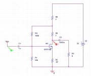
here is my entry. It outputs about 7v peak on 8ohm. R5/R6 are those little 12v xenon lamps - I actually used a peanut tube socket to house those little "tubes".
You cannot get simpler than this, :0
You can improve power output with a CCS as load but that messes up the simplicity which appears to be your desire here.
Attachments
tlf9999 said:
that requires a pre-amp, which if combined is no simpler than a jlh. You may also try the PLH or the new cascoding amp from Nelson.
here is my entry. It outputs about 7v peak on 8ohm. R5/R6 are those little 12v xenon lamps - I actually used a peanut tube socket to house those little "tubes".
You cannot get simpler than this, :0
You can improve power output with a CCS as load but that messes up the simplicity which appears to be your desire here.
Yes, it requires a preamp for standard speaker. But I can guarantee very good sound quality, compared to common source solution. Output impedance of the Follower is considerably lower, also the distortion is lower. Comparison tests with ZEN structures were done.
If connected with sensitive speakers, the preamp is not needed.
I do not try to vote for it , just an alternative to well-known circuits.
")
Hello,
Go to Elliot Sound Products web site and take a look at what used to be know as the "Elcheapo" amplifier, I think it now goes under "Simple Current Feedback Amplifier" Its very easy to build and can be built with a single or duel power supply.
I have used a modified version for months with no problems.
gives 60watts with the right voltage.
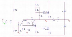
here is the jlh in mosfet configuration.
as is, it runs in class B and is pretty cool. You can dial up the bias to get it into class A entirely or play somewhere in between.
I have been runing this for over 10 years now without any ill effect (on me and on the sound).
it is simple, and good.
It is in single rail but can run on dual rails as well. R9 adjusts bias and R14 output DC point.
I was affraid of posting this at the JLh thread as the experts there kept telling me that MOSFET JLH doesn't work.
Attachments
No reason to be afraid m8 .... if you read the thread closely, you can see that the conclusion was that it did work.. anyways,
Geoff and I concluded that there are serveral reason why not to recommend a MOSFET JLH as a project: cross-conduction, Bias stability, Bias-Vsupply dependence and turn-up thump... I'm sure you're schematic sufers form some of those problems... and allthough I'm a big MOSFET JLH fan, I still wouldn't recommend it as a beginner simple project....
Simplest medium power amplifier:
Rod Elliots http://sound.westhost.com/project12.htm
The chips amplifiers , lm1875, lm3875 etc..
JLH 10W original was my first amplifier, great beginner project, cann't get much simpler
JLH 15Watt clas Ab amp
and offcourse the the first ZEN from N. Pass
maybe .. the Class A hot folower from Andrea cioffoli (?)
cheers,
Thijs
tschrama said:cross-conduction, Bias stability, Bias-Vsupply dependence and turn-up thump... I'm sure you're schematic sufers form some of those problems
It did. Here are some of my observations.
1. cross-conduction: that is just a by-product of biasing this into class A. By definition, you will have both devices conducting. nothing to get around that as long as you have a push-pull class A. it is part of the topology and exits for both bjt and MOSFET versions.
2. bias stability: it is quite stable. and it is due to the use of resistors on the phase splitter - this is why one shouldn't use CCS as a load here.
It works like this: Let's say the top output MOSFET heats up. It pulls up the output DC, which feeds more current into the input transistor. That generates a higher voltage drop on R2, thus M1 starts to conduct more -> higher voltage drop on the bootstrap resistors -> reduces Vgs on the top MOSFET -> stabilizing idle current.
The same process works for the bottom MOSFET as well.
3. Bias-vsupply dependence: yes, this is a problem, mostly reflected in the input stage as it has pretty poor PSRR.
If you are referring to bias floating with rail voltage, it is equally true for the bjt version as well.
4. turn-on thump: this can be addressed with a small (like less than 22uf) capacitor on the input transistor's base (C5). the thump is due to the charging up of C5.
The beauty of this thing, in my view, is a) its ability to handle really tough loads, even capacitive loads. b) its robustness, even with cheap transistors. I have used d2pak irf devices for headphone amps, and to220 irf devices for as power amp as well. With a pair of to246 devices, it is practically indestructible.
tlf9999 said:here is the jlh in mosfet configuration.
as is, it runs in class B and is pretty cool. You can dial up the bias to get it into class A entirely or play somewhere in between.
I have been runing this for over 10 years now without any ill effect (on me and on the sound).
it is simple, and good.
It is in single rail but can run on dual rails as well. R9 adjusts bias and R14 output DC point.
I was affraid of posting this at the JLh thread as the experts there kept telling me that MOSFET JLH doesn't work.
hi tlf9999,
really a cool design
has anyone try out this?I am very interested.Zang
digi01 said:thanks all, for your great share
what about this one?I am going to this.because it is simple and cheaper.only 20 components I believe it must make me more fun than gainclone
Zang
Your schematic is a little bit too simple in my opinion. These are my remarks:
1) The output stage consists of darlington transistors. Because only 2 diodes are used for DC biasing, the quiescent current will be 0, and switching on and off of the output transistors will be quite slow. This will result in serious cross-over distortion, especially for low output levels and higher audio frequencies.
2) It would be better to replace R2 with a current source. This will improve supply ripple rejection.
If you are looking for a real simple amplifier, you could consider kit PL2050. Note that the output transistors of this design are darlingtons (use TIP142 and TIP147).
CornelisJ said:If you are looking for a real simple amplifier, you could consider kit PL2050.
I have built a similar circuitry. It is essentially the jlh front+vas + traditional complementory EF output. or NAD3020.
I built one like that, but prefer quasi-complimentory output.
- Status
- This old topic is closed. If you want to reopen this topic, contact a moderator using the "Report Post" button.
- Home
- Amplifiers
- Solid State
- looking for the simplest solid amp