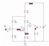
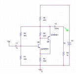
I will now give you a practical design example concerning a BC337. Note that I have included the extra capacitors C1 and C2.
The reason behind C1 is to block any residual supply noise entering the input of the emitter follower. Despite this extra capacitor you still may need a regulated supply.
I reduced idle current from 25mA to about 12mA to reduce power dissipation in the BC337 and Re. At 25mA Re would dissipate 300mW, a little bit to much if you would use a 1/4W component. Reducing the current resulted in a next advantage; the transistor needs less base current.
With a hfe of 250 the base will need 0.05mA. If we keep the advise from Jan Didden in our mind, the potential divider must pass 0.5mA to produce a stable reference.
I we apply previous formulas we get:
R1+R2=22.8K
R3=25.2K
The coupling capacitors shown at input an output are calculated for a -3dB at 5Hz.
Greetings")
The reason behind C1 is to block any residual supply noise entering the input of the emitter follower. Despite this extra capacitor you still may need a regulated supply.
I reduced idle current from 25mA to about 12mA to reduce power dissipation in the BC337 and Re. At 25mA Re would dissipate 300mW, a little bit to much if you would use a 1/4W component. Reducing the current resulted in a next advantage; the transistor needs less base current.
With a hfe of 250 the base will need 0.05mA. If we keep the advise from Jan Didden in our mind, the potential divider must pass 0.5mA to produce a stable reference.
I we apply previous formulas we get:
R1+R2=22.8K
R3=25.2K
The coupling capacitors shown at input an output are calculated for a -3dB at 5Hz.
Greetings
Amblifier said:Here is the schematic.
Nice. I think the original poster said he had a 24V supply, but that doesn't matter. The only suggestion I would have is to halve R1 and to increase R2 with the same amount to get a bit higher input Z and still have the filtered bias, but that's really splitting hairs.
Jan Didden
Amblifier said:Hello Bepp61,
The text-book emitter follwer is quite a simple circuit. .....
BD139 current gain (hfe) is about 80.
...
I hope this is of some help.
Dear Sir,
thank you very much again for your extremely kind and valuable lesson.
Nevertheless looking at a BJT datasheet for the hfe value I can see e.g from 60 to 320 ! What a wide range.
All this make me wonder about the tolerances on the calculated values of the resistors in the voltage divider.
To be more specific, the values that come from the calculation are very fixed or can vary to a some degree?
Thank you very much again for your kind help.
Kind regards,
beppe61
If you take the worst case value it will work perfectly but experience tells me that you can use 100 as typical value.
If you work in series production it might be an idea to work according to worst case but if you do this as hobby and only this single buffer you can use typical values. If you of some reason have gotten a "bad" transistor, just change it or recalulate a bit.
If you work in series production it might be an idea to work according to worst case but if you do this as hobby and only this single buffer you can use typical values. If you of some reason have gotten a "bad" transistor, just change it or recalulate a bit.
peranders said:If you take the worst case value it will work perfectly but experience tells me that you can use 100 as typical value.
If you work in series production it might be an idea to work according to worst case but if you do this as hobby and only this single buffer you can use typical values. If you of some reason have gotten a "bad" transistor, just change it or recalulate a bit.
Dear Mr. Peranders,
thank you so much for your extremely kind and helpful reply.
Kind regards,
beppe61
peranders said:A BJT has higher gm (transconductance) which is positive when it comes to distortion.
here is looking for a buffer, doesn't he? in that sense, gain doesn't matter nearly as much.
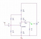
Here is my try.
it works over a wide variety of supply voltage and devices (I used irf510 here because it is cheap). very insensitive to component value. If you drop a bjt there, just down down R1. I usually adjust R1 so that the D idles at about 50% of supply voltage.
if you want to have gain, pick out the output at D of the mosfet (4x gain), or the joint of R5/R6 (2.5x gain). Otherwise, at the S for a follower.
Attachments
Originally posted by tlf9999
> here is looking for a buffer, doesn't he?
in that sense, gain doesn't matter nearly as much.
Here is my try.
Dear Sir,
thank you so much for your extremely kind and valuable reply.
This is indeed what I am looking for to drive my power amp with the signal coming from the CD player
It seems a very powerful buffer.
> it works over a wide variety of supply voltage and devices (I used irf510 here because it is cheap). very insensitive to component value.
very very good. Cheap and flexible.
> If you drop a bjt there, just down down R1. I usually adjust R1 so that the D idles at about 50% of supply voltage.
I like the mosfet as it operates in pure class A.
I read the mosfet are fine as long as they operate in pure class A.
I read also that are very commonly used as buffers, if I am not wrong.
> if you want to have gain, pick out the output at D of the mosfet (4x gain), or the joint of R5/R6 (2.5x gain). Otherwise, at the S for a follower.
very interesting option indeed.
This circuit reminds me of the Bride of Zen circuit by Nelson Pass.
But it is much simpler: no trim to set and a more conventional voltage supply easy to obtain with a LM317 based regulated power supply.
Have you already built it ?
What do you think about its distortion perfomance?
Thank you very much for your extremely kind and valuable reply.
Yours sincerely,
beppe61
ITALY
I built a prototype with the same circuit (slightly different value on irf510), and then a 5-channel module with FQU1n60 (a Fairchild small signal mosfet) but with R5 shorted out. I did that for two reasons:
a) the fairchild mosfet is abundant, plentyful and has a very small Cgs.
b) I only need a 2x gain and don't need the flexibility that R5 provided.
I don't have any means to measure distortion. According to sim, the said circuit (used as a follower) has about .4mv 2nd harmonics vs. a 1v output. higher order harmonics are barely visible. it is flat through 1mhz.
With the pick-up point at D (2.5x gain with the load connected), 2nd harmonics is about 1mv (vs. 2.5v output), and higher order harmonics is barely visible.
You are right, the circuit is exactly half of the zen-7 without CCS.
I like mosfets as you can run them very hot without loading down the prior stage. BJTs, espcially small signal bjts, tend to give you better distortion performance. However, if it is just a pre-amp, you can pretty much use anything reasonable and it will perform like a charm.
Here is one with 2n5551,, just to prove a point. it has about 2x gain, and 2nd harmonics at 0.5mv (a 50% improvement over the mosfet).
a) the fairchild mosfet is abundant, plentyful and has a very small Cgs.
b) I only need a 2x gain and don't need the flexibility that R5 provided.
I don't have any means to measure distortion. According to sim, the said circuit (used as a follower) has about .4mv 2nd harmonics vs. a 1v output. higher order harmonics are barely visible. it is flat through 1mhz.
With the pick-up point at D (2.5x gain with the load connected), 2nd harmonics is about 1mv (vs. 2.5v output), and higher order harmonics is barely visible.
You are right, the circuit is exactly half of the zen-7 without CCS.
I like mosfets as you can run them very hot without loading down the prior stage. BJTs, espcially small signal bjts, tend to give you better distortion performance. However, if it is just a pre-amp, you can pretty much use anything reasonable and it will perform like a charm.
Here is one with 2n5551,
, just to prove a point. it has about 2x gain, and 2nd harmonics at 0.5mv (a 50% improvement over the mosfet).Attachments
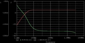
if you really want to improve performance, there is also an "ultra-linear pair" version of it, .
see the chart below. it has a slightly improved performance, especially at higher gain (pick-up at the emitter of Q6).
some performance number:
a) distortion: pretty much non-existence in the audio band, vs. .3mv without Q6.
b) frequency response: flat past 10mhz (where my simulation stops), vs. over 1mhz without Q6.
Q6 essentially functions like Q5's emitter and reduces output impedance of Q5. This is less useful in a pre-amp but more useful in a VAS driving a heavy output stage (aka parralleled power mosfets).
I have built the ultra-linear pair for pre-amp and power-amp (in a pnp+n-channel combination). In my view, the single transistor version is the way to go for pre-amp.
.see the chart below. it has a slightly improved performance, especially at higher gain (pick-up at the emitter of Q6).
some performance number:
a) distortion: pretty much non-existence in the audio band, vs. .3mv without Q6.
b) frequency response: flat past 10mhz (where my simulation stops), vs. over 1mhz without Q6.
Q6 essentially functions like Q5's emitter and reduces output impedance of Q5. This is less useful in a pre-amp but more useful in a VAS driving a heavy output stage (aka parralleled power mosfets).
I have built the ultra-linear pair for pre-amp and power-amp (in a pnp+n-channel combination). In my view, the single transistor version is the way to go for pre-amp.
Attachments
tlf9999 said:if you really want to improve performance, there is also an "ultra-linear pair" version of it,
see the chart below. it has a slightly improved performance, especially at higher gain (pick-up at the emitter of Q6).
some performance number:
a) distortion: pretty much non-existence in the audio band, vs. .3mv without Q6.
b) frequency response: flat past 10mhz (where my simulation stops), vs. over 1mhz without Q6.
Q6 essentially functions like Q5's emitter and reduces output impedance of Q5. This is less useful in a pre-amp but more useful in a VAS driving a heavy output stage (aka parralleled power mosfets).
I have built the ultra-linear pair for pre-amp and power-amp (in a pnp+n-channel combination). In my view, the single transistor version is the way to go for pre-amp.
Dear Sir,
I have been overwhelmed by the quantity and above all the quality of your excellent schematics.
What else can I say but thank you sincerely?
A help like your is very uncommon.
I have appreciated it sincerely.
I have a very low understanding of electronics but it seems to me that the circuits you propose must be very nicely sounding.
I suppose that they work all with the 32V power supply.
Am I wrong?
I am not at all forced to use a 24 V PS. 32 V is just fine.
I have in mind a nice PS based on the very common LM317.
As I am looking for a circuit to use as a line stage, the one mosfet solution with 2.5 voltage gain is perfect.
I will try in the next days to build a prototype.
The fact that the distortion is mainly of 2nd is very good and acceptable to me (some more warm in the sound).
Excuse my curiosity, but are you a professional designer?
Because I understand you have a great knowledge and expertise in audio electronics.
I would appreciated very much the opportunity to exchange some e-mails privately with you on other audio electronics and ask for your extremely valuable opinion.
Do you think if feasible? Please let me know.
Thank you sincerely again for your extremely kind, valuable and welcomed support.
Kind regards,
beppe61
beppe61 said:Excuse my curiosity, but are you a professional designer?
I am not a professional designer - I am a garbage collector / sanitary worker. I don't even have an EE and didn't go to college.
I got into this due to my desire to have simplicity and have a circuit that is more tolerant to the type of transistors used. so I added a little feedback to the existing design.
beppe61 said:I would appreciated very much the opportunity to exchange some e-mails privately with you on other audio electronics and ask for your extremely valuable opinion.
Do you think if feasible? Please let me know.
sure.
tlf9999 said:
> I am not a professional designer - I am a garbage collector / sanitary worker. I don't even have an EE and didn't go to college.
I got into this due to my desire to have simplicity and have a circuit that is more tolerant to the type of transistors used.
so I added a little feedback to the existing design.
Well, CONGRATULATIONS !
You have succeeded where I failed miserably.
I did try to understand the basics of audio electronics design but without any result.
So I am often here to ask for help.
> sure.
This is very kind and nice of you.
Then I will forward an e-mail this evening with some of my audio ramblings and problems.
Your opinions will be very much appreciated and welcome here.
Thank you so much for your greatly kind help.
KInd regards,
beppe61
TORINO
ITALY
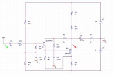
One of the draw backs of the prior single transistor pre-amp is that it cannot produce a higher gain without sacrificing the distortion.
Enclosed below is a modified JLH: with its front end and just VAS/phase splitter, to be used as a pre-amp.
Using two transistors, it is capable of providing a higher gain, and has improved distortion performance as well: foundamental at about 5v (5x gain), 2nd harmonic at 0.8mv and 3rd harmonic at 0.4mv and no visible higher harmonics.
Attachments
jan.didden and Amblifier,
Thanks for your educational posts in this ancient thread.
From your posts I came up with the following circuit for a mic buffer. All but the PS will be in the mic wand. The PS will be a regulated 9V or a 9V battery at the mic pre amp that will be near the computer.
I jiggered the resistors for the new voltage and used the 2N5210 cause I have them, they are fairly quiet and have the hfe of 250 you mentioned. Also I filtered both the capsule bias and the transistor bias resistors.
Did I do it right?
Is there a need to filter both (or either) of the supplies to the mic capsule and the transistor bias if a battery or regulated PS is used since there is a cap across the supply very nearby?
Also is an output cap necessary if the mic pre amp has a capacitive input?
Thank you for all your informative posts.
An externally hosted image should be here but it was not working when we last tested it.
Last edited:
- Status
- This old topic is closed. If you want to reopen this topic, contact a moderator using the "Report Post" button.
- Home
- Amplifiers
- Solid State
- Single bjt buffer schema kindly requested.