Hi
Here are some approximate values for an 11 step
attenuator. I suggest you use a series resistor of 15k
before reaching the 11 step switch
Arrange the resistors around the switch contacts
with the lowest resistance value being your starting point
that being the resistor which attenuates the most
( closest to ground )
The lower end of each of the resistors -( then running to ground)
can be all joined together ( as the wiper selects each individual resistance value )
R1 approx 47k ie: highest volume
R2 " 18K
R3 10K
R4 6K2
R5 3K3
R6 1K8
R7 750R
R8 390R
R9 180R
R10 100R
R11 56R ie lowest volume at the clockwise
starting point
This should give you a progressive range of levels that
hopefully will do the job
Cheers / Chris")
Here are some approximate values for an 11 step
attenuator. I suggest you use a series resistor of 15k
before reaching the 11 step switch
Arrange the resistors around the switch contacts
with the lowest resistance value being your starting point
that being the resistor which attenuates the most
( closest to ground )
The lower end of each of the resistors -( then running to ground)
can be all joined together ( as the wiper selects each individual resistance value )
R1 approx 47k ie: highest volume
R2 " 18K
R3 10K
R4 6K2
R5 3K3
R6 1K8
R7 750R
R8 390R
R9 180R
R10 100R
R11 56R ie lowest volume at the clockwise
starting point
This should give you a progressive range of levels that
hopefully will do the job
Cheers / Chris
Hi Chris,
Thanks for your reply. The total series resistance from the resistors value that you give is 87776 ohms, which is to high for my need. Do you have the resistors value for 25K total? or did I miss out anything?
Hi Leo,
Just find the kung Fu master avatar to be cool. BTW, I'm not that OLD....... Cheers!
Ipanema said:I got two single pole 11-step rotary switch, which I would like to make a series step attenuator with resistance of 25Kohms.
Just remember the switch has to be a make-before-break type.
Carlos
Hi Ipanema
The design values I suggested is a classic L Pad
Passive preamp attenuator
which should correctly load the input source
and output source so there is no untoward
frequency dipping at any volume step.
Im unsure of your intent with this ? perhaps you
could make your design intention clearer. I pictured a passive preamp as your need and perhaps I rushed in too early
Carlmart is right in that a make before break switch
is essential , the risk is switching noise ( bangs ) as
one level changes to the next. Alternatively you can
use a switch with parrallel isolated contacts, one
for switching hot and the other ground - so they are
in step with each other. A make before break switch
avoids this problem - err ..as long as it reliably makes before
breaking its last contact.
Cheers / Chris
Ipanema said:I got two single pole 11-step rotary switch, which I would like to make a series step attenuator with resistance of 25Kohms....
Can anyone provide me the resistors value? I can only find 23 steps resistor value.
Hi,
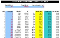
You could download a simple excel spreadsheet from Audioxpress site and calculate your own attenuator.
http://www.audioxpress.com/magsdirx/ax/addenda/index.htm
(att1.xls)
Input data:
Ratt= attenuator resistance in kohms
Rina= amplifier input resistance in kohms
Sattn= desired attenuator steps
Calculated resistor values are shown in yelow cells.
Use nearest E96 standard values.
An example is given in the picture below.
Regards,
Milan
Attachments
Question about switches and values
Hi MOAMPS,
I have a Grey Hill switch which has 12 places: 1-12. Does this mean it's really a 11-step switch? Each hop is a step? Correct?
Is the first or last place skipped when adding resistors?
Second, I also need to build a 10k switch. I tried and failed on my first try. I tried a series-shunt.
Now, I downloaded the spread sheet you recommended. Does this spread sheet provide this kind of attenuation? Do I need a constant value (Rn) to go to ground or something to that effect? What's the value depend on?
If this works, I have a larger 23-step I want to use on a balanced preamp. I'd like to work out the bugs first!
Thanks for any help you can provide!
Vince
Re: Question about switches and values
Hi Vince:
Sorry, I didn't see your post before.
You can build a 12-step attenuator using a 12 position switch. For example, you can put 55 in the Sattn cell for step 11, and 60 in the cell for step 12.
The picture above shows a 11 step attenuator because the thread starter had an 11-position switch.
I'm afraid the spreadsheet can't be used to calculate a series-shunt attenuator. It is primarily used to calculate the series type although it may also be used for the ladder type, as described in the article.
The problem with the series-shunt attenuator is that impedance changes with each different step so the attenuator design must be thought through very carefully, figuring in input impedances both of the source and the amplifier.
However, I may be able to come up with a simple spreadsheet for calculating the series-shunt attenuator step by step if you are interested. Or you can browse the internet instead; I think I've seen a few online calcualators.
Regards,
Milan
vdi_nenna said:I have a Grey Hill switch which has 12 places: 1-12. Does this mean it's really a 11-step switch? Each hop is a step? Correct?
Is the first or last place skipped when adding resistors?
Hi Vince:
Sorry, I didn't see your post before.
You can build a 12-step attenuator using a 12 position switch. For example, you can put 55 in the Sattn cell for step 11, and 60 in the cell for step 12.
The picture above shows a 11 step attenuator because the thread starter had an 11-position switch.
Second, I also need to build a 10k switch. I tried and failed on my first try. I tried a series-shunt.
I'm afraid the spreadsheet can't be used to calculate a series-shunt attenuator. It is primarily used to calculate the series type although it may also be used for the ladder type, as described in the article.
The problem with the series-shunt attenuator is that impedance changes with each different step so the attenuator design must be thought through very carefully, figuring in input impedances both of the source and the amplifier.
However, I may be able to come up with a simple spreadsheet for calculating the series-shunt attenuator step by step if you are interested. Or you can browse the internet instead; I think I've seen a few online calcualators.
Regards,
Milan
Hi there,
I'm building a valve/tube buffered inverted gainclone based on Joe Rasmussen's schematic. I've just found a 10 position dual gang rotary switch from an old R/T that I thought could make an attenuator.
I need 50k impedance, and shouldn't need the maximum volume that would otherwise be supplied by the missing 2 steps of the more common 12-step attenuator.
I have downloaded the spreadsheet above. Excuse my ignorance, I'm new to attenuators - but how do I work out the values I need? What values in what columns?
Thanks for your patience!
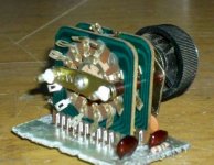
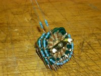
I have used Milan's spreadsheet and calculated resistor values for my 10-step attenuator. It is 50K impedence to suit a buffered amp.
I have used basic metal film resistors. Nothing fancy, but then the switch is old and probably well-used too. Perhaps the resistors are of better quality than the switch contacts
It was a bit tricky soldering between the decks, because they are so close.
Step 1 is not mute (that's why we have an "off" switch on the source!), hence the resistor to ground.
Values are:
110R, 180R, 360R, 620R, 1K2, 2K2, 3K6, 6K2, 11K, 22K.
This equates to attenuation of:
-53dB, -44.7, -37.7, -31.9, -26.1, -20.6, -15.6, -10.7, -5.8, -0.4.
It will be a few weeks yet before I know how it will sound, or if the steps are okay. But I will not be complaining -- the whole thing cost me about $3.
Attachments
- Status
- This old topic is closed. If you want to reopen this topic, contact a moderator using the "Report Post" button.
- Home
- Amplifiers
- Solid State
- Series step attenuator