First, it's great to be a part of your forum, and I hope that I posted this in the correct section. On to the issue, I blew out one of the MOSFET rectifiers in my Rockford Fosgate bd 1000.1 amplifier and need to replace it. It's an International Rectifier 6215. I have a new one already, but the problem is that I don't know how to remove the old one from the heatsink board that it is attached to. My best guess would be that it's epoxied on, but I have no idea. Does anyone have any idea how to remove it from the heat sink that it's attached to? As well, installation tips (how to attach the new rectifier to the board again) would be great. Here's a picture of what I'm talking about (You may need to refresh it to get it to load). Thanks for any help!
An externally hosted image should be here but it was not working when we last tested it.
I'm not sure if anything else was blown. The face was completely blown off that rectifier. The damage that you see done to it was the damage that was done when I opened the amp up, so I figured I would start there and see where I could get. In terms of physical damage, nothing else looks damaged, but I know that doesn't mean that nothing else is actually damaged.
FWIW -- I wouldn't be at all surprised if something else is blown; try bringing the amp up through a current limiter the first time you fire it up so you can check it out under slightly saner conditions. At least that part is not expensive.
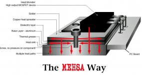
See the attached image, it details the Rockford-Fosgate MEHSA attachment technlogy. Looks like it's wave soldered to a copper strip which is in turn heat-sunk. This may be a bitch to repair with appropriate thermal effeciency...
Wes
See the attached image, it details the Rockford-Fosgate MEHSA attachment technlogy. Looks like it's wave soldered to a copper strip which is in turn heat-sunk. This may be a bitch to repair with appropriate thermal effeciency...
Wes
Attachments
That's not a rectifier, it's a p-channel mosfet. You have at least 3 blown 6215s and 3 blown 3415s. Generally it only blows out one set but I've seen them with all output FETs blown.
You can remove them with a large soldering iron or a small butane torch (like those sold at Radio Shack).
These amplifiers are generally easy to repair. Replacing FETs and gate resistors usually gets them going. If the 5 pin low-side-driver was damaged, the opto-isolator may also be damaged. The opto-isolator prevents the blown output stage from doing any further damage to the driver components.
If you're going to try to repair it, post any other questions you may have here.
Hello
I am working with this same model of amp right now. The unit is going in protection mode. I found
some bad output Mosfets. Some are still good but I’m going to replace them as a set. I see that they have them soldered directly to the PC board. Now
it was mentioned earlier that a large soldering iron
could be used to remove them. My question is what about mounting the new ones? Do you have to use a special solder for this or will standard 60/40 do the job. And what about heat? Its one thing to remove the old ones because their bad anyway. But what’s the best method of replacement of the new devices so that they don’t get heat damaged?
Thanks
I use standard solder and have never had a problem.
When replacing the transistors, I recommend tinning the back of them. It assures that the entire back of the transistor is goiing to be soldered to the strip. Some transistors don't readily accept solder and will not be soldered properly if this isn't done. If you have an adjustable iron, set it no higher than 700°F when tinning them. To make sure that they all survived the tinning, check them with an ohm meter to make sure they are not shorted or leaking.
When mounting the transistor to the insulator, it seems that heating the strip with a 'small' torch is a better method than heating the transistor with an iron. When heating the strip, the transistor only gets hot enough to melt the solder. When heating the transistor directly, it will get hotter because the iron will have to be on it long enough to heat the strip to the melting point of the solder.
Ok I have replaced the output transistors only part of them
were bad but I replaced them all. I also replaced the two 5 pin mosfet driver ICs for good measure. However when I power
the unit up it is still going into protection mode. Just wonder
what I could have missed. I was going
to check the protection circuit itself but its not clear
exactly to which components are responsible for making
it up.
Any help appreciated.
thanks
Double-check the newly replaced FETs. Sometimes they fail when they're being soldered in place.
Check the gate drive resistors. If one is defective, it's usually obvious when you power it up because it blows the new FETs (often explosively).
If you still have the drivers, check the to see if they're shorted. When they fail, they typically take out the optocouplers.
The overcurrent protection is provided by the 2 channel surface mount op-amp near the low value surface mount resistors (U18 - near the corner of the board). If overcurrent is tripping, pin 7 of the op-amp will go high. Monitor pin 7 during the delay time, it should be low. If it's always near the voltage on pin 8, it's likely defective. This drives pin 3 of u21 (through a diode, I think).
You also need to check the op-amp near the center of the board (u21). There is a surface mount electrolytic near the op-amp (c51). When the op-amp fails, it leaks negative rail voltage to the positive terminal of the cap. If you see negative voltage on the positive terminal, replace the op-amp. In normal operation, the cap charges from 0-~7 volts. This is the delay for the amp to switch on. This is a simple comparator. As soon as the voltage on pin 6 is higher than the voltage on pin 5, the output will toggle low and the amp will release the output.
On some amplifiers, it's feasible to defeat the protection circuit (for troubleshooting) but that's not the case with this amp. If there is a fault on the outputs causing the overcurrent to trip and you defeat the protection, it will destroy the outputs when the outputs are switched on.
As far as I know, Rockford has not yet released this schematic so you may have to sketch out your own schematic of the various sections.
I have just repaired one of these MEHSA amplifiers (model punch 301x). It's a shame how Rockford Fosgate quality has gone down and down, including this ridiculous MEHSA system that provides no other advantage than manufacturing labour cost reduction (it's no longer required to mount the power devices manually).
It does not work as the picture shows, since the power devices are soldered to a copper layer of negligible thickness (similar to a PCB), that is coupled to a thin aluminium sheet (1.5mm) by means of a thick insulation layer. This gives no advantage in comparison with a standard mica/thermal compound junction.
Furthermore, the aluminium sheet is poorly fixed to the heatsink with 4cm spaced screws withot washers, and it's so thin that it bents badly after it's heated and when the screws are tightened. So it's quite hard to distribute thermal compound well in order to fill all the air gaps and get good coupling between the aluminium sheet and the heatsink.
I used a small propane torch to remove the four blown (exploded) MTP50N06V devices and a 150W soldering iron and fresh solder to mount the new IRFZ48V ones. Gate capacitance is a bit higher now, but the control circuit provides plenty of dead time so there were no cross-conduction issues observed (60Khz clock with only 13us effective on-time).
It's a shame that they used only two pairs of .028 ohm 42A cheapo-MOSFETs for the PSU in that design, because each device will have to conduct more than 40A peak when the amplifier is driving 2 ohms per channel as rated. This is 50W peak dissipation per PSU transistor, 200W peak in total, not to mention the heat produced by the output devices of the four channels (with a tiny die-cast heatsink of 25x25cm). Considering the inefficient MEHSA system and the amount of hype and overrating associated with these amplifiers (some people claim them to be 1-ohm stable!!), it's no wonder to see them blowing so much. Fortunately, here in Europe they are seldom seen because they are sold at almost 3 times the USA price.
I hope it to be much more reliable now with the IRFZ48V devices, since these feature only 0.012ohm rds-on. I was tempted to remove all the MEHSA system and couple all the power devices directly to the heatsink with traditional mica sheets, but it would have been too much work not to be paid.
Also, it's a shame that these amplifiers don't have built-in fuses of proper size, because almost all chinese ones have. Since most people install them with no other fuse than a huge main one of 100 to 200A, built-in fuses usually prevent catastrophic failures (no fire, smoke or exploded devices).
Thanks for the reply.
They appear to be ok I checked them after I soldered
them to the sink and after I soldered the mosfets back in circuit. All checked good
are it because of thier interconnection with the drivers but I
was unable to find the number anywhere to retrieve a datasheet on them.
There is a pic below.
I will look into the other items you mentioned and report back Thanks.
Double-check the newly replaced FETs. Sometimes they fail when they're being soldered in place
They appear to be ok I checked them after I soldered
them to the sink and after I soldered the mosfets back in circuit. All checked good
All of them checked ok.Check the gate drive resistors. If one is defective, it's usually obvious when you power it up because it blows the new FETs (often explosively).
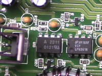
I checked them they are not shorted. In fact they may be ok. I replaced them as a precautionary measure given that they were inexpensive. Just in case there was some sort of intermittent failure. Speaking of the optocouplers it appears that U9 and U15If you still have the drivers, check the to see if they're shorted. When they fail, they typically take out the optocouplers.
are it because of thier interconnection with the drivers but I
was unable to find the number anywhere to retrieve a datasheet on them.
There is a pic below.
I will look into the other items you mentioned and report back Thanks.
Attachments
The overcurrent protection is provided by the 2 channel surface mount op-amp near the low value surface mount resistors (U18 - near the corner of the board). If overcurrent is tripping, pin 7 of the op-amp will go high. Monitor pin 7 during the delay time, it should be low. If it's always near the voltage on pin 8, it's likely defective. This drives pin 3 of u21 (through a diode, I think).
You also need to check the op-amp near the center of the board (u21). There is a surface mount electrolytic near the op-amp (c51). When the op-amp fails, it leaks negative rail voltage to the positive terminal of the cap. If you see negative voltage on the positive terminal, replace the op-amp. In normal operation, the cap charges from 0-~7 volts. This is the delay for the amp to switch on. This is a simple comparator. As soon as the voltage on pin 6 is higher than the voltage on pin 5, the output will toggle low and the amp will release the output.
Ok here are the voltage test results.
U18, pin 8 is at constant 9.7vdc.
Pin 7 is at constant -8.3vdc.
C51 is at constant -6vdc on positive side
of cap.
So it appears that I will have to replace a couple of
Op amps. If you suspect any other components or have any
suggestions the input would be appreciated.
Thanks.
U21 looks to be defective. The other op-amp output is supposed to be low. If it were high, that would indicate overcurrent detection.
If you have to order the op-amp, order several in case the other needs to be changed or in case you damage the new one when installing it.
Ok..I went ahead and replaced both Op amps and C51 and so far
so good. By the way could you tell me what the number for U15
is? Its on the pic of one of my last posts. I cant seem to find
the number for it (maybe its incomplete) I would like to have
a datasheet for future reference.
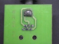
This unit just happend to have one of those plug in
external bass controls. I will have to rework the connections
on it before I let it go. (Check out the pic)
Looks like someone got a bit carried away with thier 140 watt
solder gun anyway thanks for your time.
Attachments
- Status
- This old topic is closed. If you want to reopen this topic, contact a moderator using the "Report Post" button.
- Home
- Amplifiers
- Solid State
- Help with removing and replacing rectifier (IRF 6125) from a heatsink board