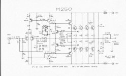
I got bored, so I built a discrete amplifier from a schematic I found somewhere on the web.
I dont have any of the transistors they had on the schematic, except fot the BC556, BC557 small signals.
So I used 2sb688 and 2sd718 for the outputs, and im only using one pair. I used some random drivers I had in my stash, when I repaired peavey amps, and I used those for the driver stages.
It works, and sounds ok to a certain extent. I got my rails at +/- 25v, and current limited for a reason, so I dont blow anything up. (using SMPS).
The problem is, it sounds ok, but when I start to turn it up to a normal volume, Ill hear a high pitch "clicks" and "pops" in the audio with the beats. if I turn it louder, itll start to pound the 15" speaker i have, but the clicks and pops, become a high pitch squeal kinda.
then itll start to go into overcurrent shutdown (protects SMPS and amp). (ill see the bias LED used in the current source follower start to sag). I have like .1 DC offset, so its not bad. no hum, nothing.
Any ideas? If I remove the 100n bypass cap between the +/- rails, it gets weak and distorted at all volumes.
Attachments
Well, this makes me think you've got things oscillating.
That's when I start putting capacitance from rails to ground at the far ends of the rails.
One thing I have found in other designs similar to this in that the current source reference is shared is feedback problems between current sources. I usually bypass the diode reference using a cap to eliminate transfer of signals from one current source to the other...
Other things may be coming up from your choice of transistors too, so perhaps some more stabilization is in order.
uhm, if I do cap from rails to ground it makes it worse.
If i do a cap from rail to rail, it makes it a tad better.
You kinda lost me a little bit with the diode current source blah blah. I dont understand how discrete amps work that well. I can repair them, and build them, but never could analyze them.
If i do a cap from rail to rail, it makes it a tad better.
You kinda lost me a little bit with the diode current source blah blah. I dont understand how discrete amps work that well. I can repair them, and build them, but never could analyze them.
Ah, you have now clearly indicated your problem: Breadboard.
Big no-no when it comes to amplifiers like this. The problem is the capacitance of the board itself. It's like putting little capacitors and weak connections on everything in the amplifier.
I've had very little success in the field of breadboarding amplifiers with such high open-loop gain or high speed.
I fixed it!! Stupid bias.
Ok, I noticed at quiescent current, it was just below the .7v Well, that was half my problem. I cranked the pot all the way up, couldnt get it above 1v, and it cleaned the sound up abit, but not enough.
I got rid of that 15ohm resistor between the pot and the emitter, and it jumpt to about 3v, so I backed it off about half way on the pot, now all distortion is gone, the sound is very clean.
I hooked my +/-44v supply up, and it woke my grandma. oops, its 1 am here. thats bad.
Im guessing because the transistor I was using had a different beta, and affected the bias on the first complementary pair. I dunno, but it worked.
VI limiter circuit is activating ? What happens if you remove T6 and T7?
Try adding a capacitor of say 100nF over the green LED.
Generally you can build amps on veroboard but you have to be VERY careful with the layout, and not have unneccesarily long tracks. I built a P3A on veroboard and it worked fine but I was ultra careful.
As for a breadboard, i wouldn't try it, especially dealing with the high currents in the output stage. A friend of mine tried to make a simple LM317T based PSU on breadboard, and ended up melting part of the breadboard.

- Status
- This old topic is closed. If you want to reopen this topic, contact a moderator using the "Report Post" button.
- Home
- Amplifiers
- Solid State
- need assistance