Re: Just lucky actually.
You askin me? You asking ME? Taxidriver? Robert de Niro
I don't know wether you are kidding or are really asking?
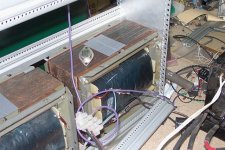
1/4" seems much but it's not forbidden to have VERY wide air gap. Normally we talk 1 mm (0.039") or so.
HarryHaller said:Hmmmm......I wonder what that 1/4 inch air gap was in there for?
Can you tell us Peranders?
You askin me? You asking ME? Taxidriver? Robert de Niro
I don't know wether you are kidding or are really asking?
1/4" seems much but it's not forbidden to have VERY wide air gap. Normally we talk 1 mm (0.039") or so.
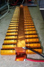
2200uF 35v times fifty-two.
Copper shim joining caps is I think 23mm x 0.25mm. Approx same cross sectional area as 3mm diameter wire but extra good at high frequencies because of low skin effect. Total ESR of caps is way lower than one big cap. Besides, that's what the junk box had.")
GP.
Copper shim joining caps is I think 23mm x 0.25mm. Approx same cross sectional area as 3mm diameter wire but extra good at high frequencies because of low skin effect. Total ESR of caps is way lower than one big cap. Besides, that's what the junk box had.
GP.
Attachments
really asking........
http://www.coilws.com/magneticandhow.html
"So, it is very important in a choke or inductor design, not to drive the core into saturation by increasing the current (AC or DC). Usually it is the DC current that saturates the core since it is a constant current, and drives the core to a certain flux level."
Sorry I will ask someone else next time since you don't understand my concern with large DC currents in ferrous inductors.
http://www.maneng.com.au/dcchokes.htm
H.H.
Re: really asking........
What were you asking about really? This big mamas was designed for much DC, or? I think they were designed for MUCH more than 3 A. Check the wire dimensions!
I wonder how the frequency characteristics are? The inductors are made of laminated iron.
HarryHaller said:
Sorry I will ask someone else next time since you don't understand my concern with large DC currents in ferrous inductors.
What were you asking about really? This big mamas was designed for much DC, or? I think they were designed for MUCH more than 3 A. Check the wire dimensions!
I wonder how the frequency characteristics are? The inductors are made of laminated iron.
Re: really asking........
If the core had no airgap then it would indeed saturate easily with dc and what's more it would store very little energy. We need to have stored energy to swing the mosfet source and consequently the load below the zero volt rail on the negative half cycle. With a gapped magnetic circuit the vast majority of the stored energy is contained in the airgap flux. A gapped inductor is much much more resistant to dc saturation than an ungapped one. However for a given amount of turns and iron the inductance is much lower. If I reduce the gap on my chokes from 1mm to zero the inductance would rise by a factor of perhaps 100. Great for AC, rotten for DC.
I seem to remember (from 1990) that those chokes with the original large gap were good for 25 amps dc. Actual working current was 15 amps dc. Not sure what current they would saturate at with the smaller gap but it seems to be a least 10 amps judging by the fact they will tolerate 240vac @ 50Hz.
GP.
HarryHaller said:http://www.coilws.com/magneticandhow.html
"So, it is very important in a choke or inductor design, not to drive the core into saturation by increasing the current (AC or DC). Usually it is the DC current that saturates the core since it is a constant current, and drives the core to a certain flux level."
Sorry I will ask someone else next time since you don't understand my concern with large DC currents in ferrous inductors.
http://www.maneng.com.au/dcchokes.htm
H.H.
If the core had no airgap then it would indeed saturate easily with dc and what's more it would store very little energy. We need to have stored energy to swing the mosfet source and consequently the load below the zero volt rail on the negative half cycle. With a gapped magnetic circuit the vast majority of the stored energy is contained in the airgap flux. A gapped inductor is much much more resistant to dc saturation than an ungapped one. However for a given amount of turns and iron the inductance is much lower. If I reduce the gap on my chokes from 1mm to zero the inductance would rise by a factor of perhaps 100. Great for AC, rotten for DC.
I seem to remember (from 1990) that those chokes with the original large gap were good for 25 amps dc. Actual working current was 15 amps dc. Not sure what current they would saturate at with the smaller gap but it seems to be a least 10 amps judging by the fact they will tolerate 240vac @ 50Hz.
GP.
Nothing exceeds like excess...
Not sure what kind of multilayer you mean, but I was thinking of putting a second layer of caps along with theses ones. Then the junk box is just about exhausted for that type of cap. Also there will not be enough space left for the tranny and other stuff. Each (100 watt) heatsink will have it's own fan so maybe I should put "Twin Turbo" on the front panel.
I finally got the driver stage going properly tonite (Sunday) took all weekend it did. Uses a N-channel fet current source load. Has an open loop gain of about 630. One version had a gain of over 2000! Not bad for a single stage but the distortion was a bit ordinary and it had a bit of high frequency fuzz on the waveform. This one will swing 80v p/p with almost no visible distortion. It clips at 120v p/p using a 145v dc supply and a 50mA drain current. The closed loop gain of the whole amp is x10 and even though I have used no pole splitting caps or other compensation band-aids it seems to be as stable as a rock. The sound is really nice - to my biased ears anyway. Look out AKSA, when its done I will definitely lug it over to your place, that is if shifting it's weight 20 miles or so doesn't upset the balance of the whole city of Melbourne.
Also, in the spirit of overkill, and excessiveness generally, I am thinking of bootstrapping the top of the current source. That way the constant current load fet will have nearly a constant voltage across it. So the constant current will be *very* constant and it's slope resistance will be *very* high (currently about 22k or so) The stage gain will then be something the far side of ridiculous. We'll see.
On a more sensible note, I am thinking of sort of bootstrapping the output stage too. Put a second mosfet above the first with the top fet drain to dc supply and it's source to the drain of the existing (now bottom) mosfet. Bias the top fet about 10v above the bottom one and drive both with the same audio signal. What happens is the bottom mosfet now has a more or less constant voltage across it during the audio waveform! One less thing for it to worry about. Seeing the drain source voltage won't decrease to low values during high positive signal swings it's transconductance won't nose-dive and so there should be less distortion. The setup will need a higher dc supply voltage though so the efficiency will end up being about the same as a steam locomotive. heh heh egad, this is fun!!!
GP.
peranders said:Circlotron, since you are overdoing it
Not sure what kind of multilayer you mean, but I was thinking of putting a second layer of caps along with theses ones. Then the junk box is just about exhausted for that type of cap. Also there will not be enough space left for the tranny and other stuff. Each (100 watt) heatsink will have it's own fan so maybe I should put "Twin Turbo" on the front panel.
I finally got the driver stage going properly tonite (Sunday) took all weekend it did. Uses a N-channel fet current source load. Has an open loop gain of about 630. One version had a gain of over 2000! Not bad for a single stage
but the distortion was a bit ordinary and it had a bit of high frequency fuzz on the waveform. This one will swing 80v p/p with almost no visible distortion. It clips at 120v p/p using a 145v dc supply and a 50mA drain current. The closed loop gain of the whole amp is x10 and even though I have used no pole splitting caps or other compensation band-aids it seems to be as stable as a rock. The sound is really nice - to my biased ears anyway. Look out AKSA, when its done I will definitely lug it over to your place, that is if shifting it's weight 20 miles or so doesn't upset the balance of the whole city of Melbourne. Also, in the spirit of overkill, and excessiveness generally, I am thinking of bootstrapping the top of the current source. That way the constant current load fet will have nearly a constant voltage across it. So the constant current will be *very* constant and it's slope resistance will be *very* high (currently about 22k or so) The stage gain will then be something the far side of ridiculous. We'll see.
On a more sensible note, I am thinking of sort of bootstrapping the output stage too. Put a second mosfet above the first with the top fet drain to dc supply and it's source to the drain of the existing (now bottom) mosfet. Bias the top fet about 10v above the bottom one and drive both with the same audio signal. What happens is the bottom mosfet now has a more or less constant voltage across it during the audio waveform! One less thing for it to worry about. Seeing the drain source voltage won't decrease to low values during high positive signal swings it's transconductance won't nose-dive and so there should be less distortion. The setup will need a higher dc supply voltage though so the efficiency will end up being about the same as a steam locomotive. heh heh egad, this is fun!!!
GP.
Gate-source capacitance modulation?
With my driver cct I am using a 100k & 1M gain setting resistors and if I run the thing open loop the distortion is reasonable but if I short the 100k in series with the signal, the distortion improves quite a bit. What is happenening here? Is the gate-source capacitance changing with the instantaneous voltage on it, and a low impedance drive just bulldozes through, but with the 100k in series the capacitance variation distorts the signal? Sort of like capacitors causing distortion as per another thread here? I have never come across this before. The only solution I can see it to use a buffer upstream to drive lower value feedback resistors. I don't really want to do that, so what can I do?
GP.
New output stage.
Going to try this output stage as per 2 posts ago. Also I found out my output stage distortion problems that I thought were caused by an unsuitable fet, or the bootstrapping going bad; well it turned out I had been ultra-conservative and left a 10k gate resistor on the fet. I mean duhh... So now it's 470R and works much better.
GP
Attachments
I tried bootstrapping again and the open-loop gain rose from 190 ( I think I got it wrong in an earlier post) to 260. I thought it would go sky high so that was a surprise. Maybe I should disconnect the output stage and see what it is then. Maybe it is loading the driver a little.
For my next trick, as a current source I am going to use a 3.3v low dropout 3 terminal regulator wired as a current source, i.e. put a 75R resistor from output to ground leg and the (floating) reg sinks constant current between input and ground pin. The one I tried on the bench had a slope resistance (*change* in current versus *change* in voltage) of about 4 megohms so that was good. The specs show 60 dB ripple rejection to about 10kHz then gradually falling above that. So I think it would work alright at audio frequencies.
The reg will only stand about 35 volts max input to output so what I will do is put it in the source leg of the existing current fet in place of the resistor. In theory this should multiply the 4 megohms of the reg by the voltage gain of the fet! On the bench though it actually showed about 300k slope resistance. Not sure what's going on there. Any ideas?
GP.
Re: Nothing exceeds like excess...
I ment cut the long copper band into smaller pieces. Make this "cap band" like a square (if you really want to go extreme). This is not important, only cool.
Circlotron said:
Not sure what kind of multilayer you mean, but I was thinking of putting a second layer of caps along with theses ones. Then the junk box is just about exhausted for that type of cap. Also there will not be enough space left for the tranny and other stuff. Each (100 watt) heatsink will have it's own fan so maybe I should put "Twin Turbo" on the front panel.
I ment cut the long copper band into smaller pieces. Make this "cap band" like a square (if you really want to go extreme). This is not important, only cool.
Circlotron,
Intriguing Schwartzenegger-esque project! And progress is apace: seems to be developing by the hour - how about an updated schematic to show the latest state?
I would like to ask about the output bootstrap. What was the reason for this again? You see, at first glance it seems to me that since both devices are loading the driver stage that gains through shielding the lower FET might be lost on the upper FET. Perhaps if the upper FET was not loading the driver stage it would be a more effective circuit. For example, if the gate of the upper FET was tied 15V above the source of the lower FET. Might be a little more complicated to implement.
My worth.
BAM
(still trying to figure out what that photo is...woman in lilac dress in front of a control panel?)
Intriguing Schwartzenegger-esque project! And progress is apace: seems to be developing by the hour - how about an updated schematic to show the latest state?
I would like to ask about the output bootstrap. What was the reason for this again? You see, at first glance it seems to me that since both devices are loading the driver stage that gains through shielding the lower FET might be lost on the upper FET. Perhaps if the upper FET was not loading the driver stage it would be a more effective circuit. For example, if the gate of the upper FET was tied 15V above the source of the lower FET. Might be a little more complicated to implement.
My
worth.BAM
(still trying to figure out what that photo is...woman in lilac dress in front of a control panel?)
Graham,
Interesting circuit; constant voltage source follower, no less.
You go to a lot of trouble to avoid Vgs (bias) changes by placing a constant voltage across the lower FET, but in fact it will change considerably anyway because of the variation in current.
This will cause second harmonic distortion, which is no big deal, but rather than lose headroom and sacrifice efficiency with a second FET atop the source follower, why not run your source follower in CFP with a bipolar driver, thus reducing to very low levels the variation in Vgs, and scotching the constant voltage idea which in truth contributes far less distortion than the bias changes caused by current variations through the FET?
The circuit is below, and works well; the current source is replaced by your inductive load (with a blocking cap for the speaker, incidentally). I have tried it, and it forms the basis of my Glass Harmony SE amp using mosfets, which you must hear some time....
A PSpice analysis would reveal this, I feel, but I don't have such a beast on my PC to check it out.
Cheers,
Hugh
Aspen Amplifiers
aksaonline.com
traderbam said:(still trying to figure out what that photo is...woman in lilac dress in front of a control panel?)
The woman is Brigitte Helm in Fritz Lang's 1926 film Metropolis. She is an evil robot, the "twin" of a woman of which butter wouldn't melt in her mouth. She is about to sabotage the underground city's pumping station control panel. The web has a jillion references to this nifty movie.
GP.

- Status
- This old topic is closed. If you want to reopen this topic, contact a moderator using the "Report Post" button.
- Home
- Amplifiers
- Solid State
- My first ever Class A amp.