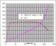
Here's a graph of choke AC voltage, current and inductance. This is the tranny with the bobbin, using the green winding only. With both windings in series the inductance is about 960mH. Here it is averaging 258mH. The maximum AC current before the onset of saturation is shown clearly by the drooping inductance and the steepening of the amps graph. I chose 2.16 amps AC as the max, the peak of which is 2.16 x 1.414 = 3.05 amps. So it will take ~3 amps DC. This is with an airgap of 0.25mm. Wider gap = lower inductance = more amps capability.
Attachments
Status report:
Recieved ten PSU caps today, 6800µF 40 Rifa.
I also made my own choke for the power supply, 60-70 turns of 1,4mm wire on a EI84 core. Hope it can take 6 A DC without acting like a fuse...
Power supply will look somethinh like this:
24V Transf. - 35 A Bridge rect. - 15000µF - choke - 10x6800µF.
There will also be extra caps close to each output stage (15000uF/ channel). First and last caps will be decoupled with
4µF GEC paper in oils (motor run caps, I think)
Still looking for some proper heatsinks and an enclosure that can swallow this beast...
Had some spare time today so I sat down and breadboarded a prototype just to see if the concept worked.
This version is quite different from the planned final amp, but the basic topology is the same. 12AU7 (ECC83) input stage with one triode as VAS and the other as a cathode follower. The output stage is a single IRFP150 operated at 16V rail and 1,5A bias.
Well, did it work then?
Yes, after some minor trouble with the tube circuitry it does.
I was a bit nervous about the bass response but that part seems rather fine. Not perfect maybe, but good enough.
What worries me more is a quite raw and nasty midrange.
I hope that has something to do with the fact that this is only a very primitive prototype using junk box components glued to a chipboard.
The adventure begins.
Time to attach a sinewave to one end and a 'scope to the other and have a look-see. Also, have yougot a resistor of several hundred ohms in series with the fet gate? Without one the amps may be only marginally stable and right on the verge of taking off. In fact it may be doing just that on peaks.
Yesterday, AKSA came around to my house to play, and he brought a pair of most excellent speakers with him as well as two of his Aspen Glass Harmony monoblocks. Of course I fully expected them to sound better than my amp but I was surprised at how reasonable mine sounded by comparison. What sounded different was things like background hiss from the recording; with mine it was just hiss but with the Glass Harmonies it was like you could have reached over and run your hand through it and counted those tiny specks of noise. Also the bass on mine was a just a little muddy by comparison but in fairness we were using 4 ohm speakers which my amp is not intended for. His amp just dissapeared after a short while, leaving only the performance there to be listened to while mine didn't achieve this to such a great extent. You were still aware you were listening to electronics but I would have never noticed this if I had not had something to compare it to. The sound of mine is extremely easy to listen to anyway. No obvious sonic vices and way better than what you might expect seeing it has no magic power cord, no name-brand capacitors, no plastic peeled off the electro's, no specific coloured wire, no special solder, resistors randomly oriented, no blue led, no wood or stone in the chassis construction, and complete disregard for whatever might be currently be fashionable to the golden ear brigade.")
Time to attach a sinewave to one end and a 'scope to the other and have a look-see. Also, have yougot a resistor of several hundred ohms in series with the fet gate? Without one the amps may be only marginally stable and right on the verge of taking off. In fact it may be doing just that on peaks.
Yesterday, AKSA came around to my house to play, and he brought a pair of most excellent speakers with him as well as two of his Aspen Glass Harmony monoblocks. Of course I fully expected them to sound better than my amp but I was surprised at how reasonable mine sounded by comparison. What sounded different was things like background hiss from the recording; with mine it was just hiss but with the Glass Harmonies it was like you could have reached over and run your hand through it and counted those tiny specks of noise. Also the bass on mine was a just a little muddy by comparison but in fairness we were using 4 ohm speakers which my amp is not intended for. His amp just dissapeared after a short while, leaving only the performance there to be listened to while mine didn't achieve this to such a great extent. You were still aware you were listening to electronics but I would have never noticed this if I had not had something to compare it to. The sound of mine is extremely easy to listen to anyway. No obvious sonic vices and way better than what you might expect seeing it has no magic power cord, no name-brand capacitors, no plastic peeled off the electro's, no specific coloured wire, no special solder, resistors randomly oriented, no blue led, no wood or stone in the chassis construction, and complete disregard for whatever might be currently be fashionable to the golden ear brigade.
I dont have neither a ´scope or a tone generator, but a scope will arrive in the middle of next week (30 USD second hand )
and as tone generator I´m going to use my CDP with a test CD containing multiple test tones and frequency sweeps 18-22000Hz.
The raw and nasty midrange I talked about pretty much dissapeared after increasing the bias to 2A and letting the amp warm up for an our or so. Also the bass was better than I first thought.
I noticed one strange thing though. When the amp is switched on the current through the Mosfet slowly rises for a couple of seconds then it jumps up to about 10 A for a second or so before it settles at 2A. I must have something to do with the tube input stage, cause it doesn´t happen if the tube circuit is disconnected.
Probably it can be cured by some kind of softstart for the tube circuit or by firing up the tube before the Mosfet.
Something has to be done, this cant be healthy neither for the mosfet or the rectifier.
)and as tone generator I´m going to use my CDP with a test CD containing multiple test tones and frequency sweeps 18-22000Hz.
The raw and nasty midrange I talked about pretty much dissapeared after increasing the bias to 2A and letting the amp warm up for an our or so. Also the bass was better than I first thought.
I noticed one strange thing though. When the amp is switched on the current through the Mosfet slowly rises for a couple of seconds then it jumps up to about 10 A for a second or so before it settles at 2A. I must have something to do with the tube input stage, cause it doesn´t happen if the tube circuit is disconnected.
Probably it can be cured by some kind of softstart for the tube circuit or by firing up the tube before the Mosfet.
Something has to be done, this cant be healthy neither for the mosfet or the rectifier.
Now it´s started
Went to the store this afternoon and returned with 700 SEK (70-75 USD) worth of sheet metal, bolts, nuts, copper wire, relays, silicon grease (or whatever it´s called, the stuff that increases the heat transfer to the heatsinks) and a lot of other stuff.
I´ve also made plans for the chassis construction.
A two level design with the big toroid transformer and the PSU caps at the bottom and the chokes on the next floor above. Heatsinks on the sides. Size 25x40x17 cm (WxDxH) excluding the heatsinks.
This is a rather simplified explanation of a quite complex design, I would need pictures to explain what I mean.
Hopefully I can take some photographs during the building process, but I cannot make any promises.
Status report:
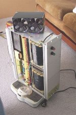
The bottom plate has been machined and all the PSU components are in position. Only a little wiring left (most have been done) before it´s time to test run the PSU.
It´s quite heavy already and still the chokes, heatsinks and most of the chassis are missing
The bottom plate has been machined and all the PSU components are in position. Only a little wiring left (most have been done) before it´s time to test run the PSU.
It´s quite heavy already and still the chokes, heatsinks and most of the chassis are missing
Yeah, I know all about heavy.  Mine weighed in at 51kg before it was finished. I bet the amount of work you do on your amp increases exponentially as it nears it's finish! Good stuff, Fuling.
Tubecad currently has a bit of a blurb on choke loaded amps. One of them looks remarkably familiar...
http://www.tubecad.com/page3.html
Mine weighed in at 51kg before it was finished. I bet the amount of work you do on your amp increases exponentially as it nears it's finish! Good stuff, Fuling. Tubecad currently has a bit of a blurb on choke loaded amps. One of them looks remarkably familiar...
http://www.tubecad.com/page3.html
Oh yeah, where have I seen that circuit before??
That Zen-like circuit is quite interesting too, but the input impedance seems a bit problematic so I´ll stick to the source follower. Maybe some other time if I can gather the willpower to wind the chokes. Would be the ultimate in simpicity, featuring one semiconductor per channel(ok, there´s a zener too) AND relatively high effiency.
Been thinking a bit about alternatives for a simple and cheap tube driver for this amp and I came up with the idea of using triode connected PL83:s. µ=24 Ra=1,9k, should be fine as a really grunty driver stage to handle the input capacitances of the mosfets. Most important: I already have a good stock of them...
Would love to try choke loading but since money certainly is an issue here I´ll try with a simple resistor as plate load instead.
No need to worry about that yet though since I´m planning to build the driver stage later in a separate box, there simply isn´t room for it inside the main amp chassis.
 Kilograms, not pounds.
- Status
- This old topic is closed. If you want to reopen this topic, contact a moderator using the "Report Post" button.
- Home
- Amplifiers
- Solid State
- My first ever Class A amp.