Hi,
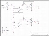
Below is an Infinite Slope Crossover circuit modelled in Orcad/PSpice. The LP section works fine, but the HP section claims there is a "node x is floating" problem between C1 and C10...I have traced it to being a problem with C1 as bypassing it corrects the problem but gives me about a 6dB rolloff! I believe this has something to do with low frequencies causing an open circuit...but that's only a guess...And why wouldn't the other caps have the same problem...
Any ideas?!
Thanks...
Gaz
P.S. Sorry about the quality...Had to drop it right down to get under limit!
Attachments
Thanks,
I'll have a go when I get home...
I can't claim to understand why it needs DC when I'm dealing with AC analysis and the rest of the circuit doesn't cause a problem. Would I have to put the resistor there when it comes to making the circuit? How come other simulation packages model it fine (such as the one from the page where I got this circuit)?
Thanks
Gaz
P Spice
Since P spice uses the Q-point of the transistors to calculate the AC model for the cuircuit it has to know what DC currents there are running in each transistor.
The opamp you use is made from a subcuircuit with alot of different transistors that all gets their model made from their Q point.
Hope it works out for you.
\Jens
Well,
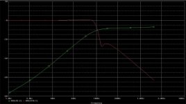
There's good news and bad news! I put a 10Meg resistor across C1 as suggested and the simulation runs (as expected). The bad news is that the response is far from what I expected...So something still isn't right!
The other thing is...To get the summed response do you just add the two graphs together? Seem to get an odd response when I try that!
Here's a quick pic of the response...
Thanks,
Gaz
Attachments
Hi,
I have attached a zip file that has all the files in it for OrCad 9 (but I'm sure it'll work for others). Please note that the infinte slope crossover is Patented...so use it for educational/non-profitable use only (or to help me fix it!!!") )
)
Thanks
Gaz
I have attached a zip file that has all the files in it for OrCad 9 (but I'm sure it'll work for others). Please note that the infinte slope crossover is Patented...so use it for educational/non-profitable use only (or to help me fix it!!!
)Thanks
Gaz
Attachments
Hi,
Thanks...All sorted now! It was 2am when I was trying to troubleshoot the circuit and just didn't see that!
I compared the circuit with a 24dB LR active Xover to see the difference. It turns out the infinite slope xover has a far steeper curve at the xover point but then after that initial steep slope it only rolls off at about 12dB. Not sure which circuit I'll use yet...Maybe both! Shouldn't be too difficult to change them using a DPDT relay!
Thanks
Gaz
- Status
- This old topic is closed. If you want to reopen this topic, contact a moderator using the "Report Post" button.
- Home
- Amplifiers
- Solid State
- PSpice Error...What's wrong?!