Following on from the work described in a previous thread, I have managed to accomplish my goal of approaching the performance of decent IC op-amps with a simple discrete circuit that can be impemented small enough to replace an IC.
The following results were achieved with through-hole components on a breadboard, and so are probably a little optmistic given that the available SMT parts tend to be inferior, but it's promising nonetheless.
I determined that the major source of distortion was not the output stage as I had first thought, but the Vas, presumably due to the nonlinear input impedance. Cascoding this stage fixed it up nicely, reducing measured distortion from worse than an OPA604 to immeasurable, maybe even better than any op-amp I currently possess.
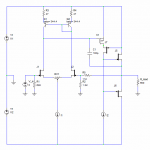
The attached schematic shows the circuit used. Compared to my first attempt, this one has degeneration resistors on the current mirror (they don't help distortion much, but they do help DC offset a lot - hopefully enough that I can do away with the adjustment pot.) and a cascoded Vas. I did try a MOSFET input stage too, since it's easier to buy dual ones compared to JFETs, but they are far too noisy so I'll have to put up with hand-matching single JFETs instead.
The following results were achieved with through-hole components on a breadboard, and so are probably a little optmistic given that the available SMT parts tend to be inferior, but it's promising nonetheless.
I determined that the major source of distortion was not the output stage as I had first thought, but the Vas, presumably due to the nonlinear input impedance. Cascoding this stage fixed it up nicely, reducing measured distortion from worse than an OPA604 to immeasurable, maybe even better than any op-amp I currently possess.
The attached schematic shows the circuit used. Compared to my first attempt, this one has degeneration resistors on the current mirror (they don't help distortion much, but they do help DC offset a lot - hopefully enough that I can do away with the adjustment pot.) and a cascoded Vas. I did try a MOSFET input stage too, since it's easier to buy dual ones compared to JFETs, but they are far too noisy so I'll have to put up with hand-matching single JFETs instead.
Attachments
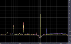
Attached to this post is a comparison of distortion at 1kHz (ignore the spiky garbage below 1kHz). For these measurements gain was set to 100, non-inverting. The red trace is my circuit: Noise is an acceptable level, no distortion components are visible above the noise. Yellow is an NE5534: Noise a bit lower than mine, but there is some 3rd harmonic present (barely visible at -112dB). Blue is an OPA604, which is thoroughly beaten.
Attachments
Very interesting.
My only question is why do you cascode this way?
It depends on VAS current mode of course, but still VAS mosfet works with low Vds, probably in "'triode range'' (??? word-by-word translation from Polish). Adding a diode or two to change the voltage on the gate of J7 may change things and I suspect you don't need rail to rail voltage swing.
Don't know if I'm right, just a suspicion...
regards
Damn! you have been faster ")
I have been planning similar project for a while now, altough I am not sure if i try to fit it at DIP8 size or if i do bigger units with bigger component count . Bipolars were on my mind, cheap as dirt and availlability is not an issue no matter where you live.
I Think i had to upgrade my soundcard before that, any recommendations on 24bit cards for measurements?
Best soundcard for audio measurements, so far:
E-MU 1212m:
http://www.emu.com/products/product.asp?category=505&subcategory=491&product=9872
RMAA data:
http://www.fixup.net/products/benchmarks/1212m2448.htm
Double the cost and you get the E-MU 1820m,
same data, but a convenient breakout box:
http://www.emu.com/products/product.asp?category=505&subcategory=491&product=9871
I cascoded like that because it only takes one component to do it. Extra components make it increasingly difficult to squeeze the circuit into the required volume, which is the main consideration. Yes, "triode range" is the right term, or you might say it's operating in the "ohmic region". It is a bit weird, but it seems to work. I did try altering the cascode bias voltage, but it's hard to measure the difference. Sims say nothing much changes.darkfenriz said:Very interesting.
My only question is why do you cascode this way?
It depends on VAS current mode of course, but still VAS mosfet works with low Vds, probably in "'triode range'' (??? word-by-word translation from Polish). Adding a diode or two to change the voltage on the gate of J7 may change things and I suspect you don't need rail to rail voltage swing.
Don't know if I'm right, just a suspicion...
regards
Nice, but how small is itboraomega said:I've tried something similar long, long time ago (12-15 years ago) with more than satisfactory results. Unfortunately, at that time, no simulation software was available to me, but practical results were more than good.

sweet!
mr evil:
very nice!
i am curious if you ever played around with this one during your investigations:
http://www.forsselltech.com/JFET Opamp.PDF
also, did you try other OPA604 parts? i saw your previous graphs in the other posts and was suprised how the OPA604 faired. just wondered if you might have a defective one?
mlloyd1
Re: sweet!
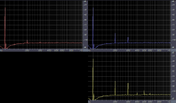
It reduces output stage distortion, as illustrated in the attached FFT. To make the effect more clear, output stage distortion was increased by loading the output with a 220 Ohm resistor, 1Vrms output voltage. The red trace is with the output stage included in the compensation; blue with normal Miller compensation around Vas only; yellow is an NE5534. As you can see, it's well worth the slightly reduced stability.Ultima Thule said:Nice, though the Miller cap from the VAS input is connected directly to the output, interesting...
Michael
I have seen that one before. Such circuits are what I looked to for examples when designing this one.mlloyd1 said:...i am curious if you ever played around with this one during your investigations:
http://www.forsselltech.com/JFET Opamp.PDF...
I have several and they all measure very similarly. It could be that I have a whole bad batch, since they all came in the same tube, but I don't think so, as my findings are consistent with the measurements seen on D. Self's site and my experience with using and listening to them over the last few years (I bought lots, then regretted it).mlloyd1 said:...also, did you try other OPA604 parts? i saw your previous graphs in the other posts and was suprised how the OPA604 faired. just wondered if you might have a defective one?
Attachments
Re: Re: sweet!
Output stage inclusive miller comp seems to be efficient just like it should, too bad that it is not applicable to power amps.
Do you have some numbers on stability with output stage inclusive miller comp.? phase margin and GWB with/without?Mr Evil said:
It reduces output stage distortion, as illustrated in the attached FFT. To make the effect more clear, output stage distortion was increased by loading the output with a 220 Ohm resistor, 1Vrms output voltage. The red trace is with the output stage included in the compensation; blue with normal Miller compensation around Vas only; yellow is an NE5534. As you can see, it's well worth the slightly reduced stability.
Output stage inclusive miller comp seems to be efficient just like it should, too bad that it is not applicable to power amps.
Re: Re: Re: sweet!
The best I can do is measure capacitive load drive capability (unity gain inverting mode with 100pF comp cap): With output stage included it will go up to 1nF. With normal Miller comp 1.2nF.
I can't measure GBP or phase margin because I don't have a signal generator that will go that high and sims are going a bit wonky at high frequency for this circuit.mzzj said:
Do you have some numbers on stability with output stage inclusive miller comp.? phase margin and GWB with/without?
Output stage inclusive miller comp seems to be efficient just like it should, too bad that it is not applicable to power amps.
The best I can do is measure capacitive load drive capability (unity gain inverting mode with 100pF comp cap): With output stage included it will go up to 1nF. With normal Miller comp 1.2nF.
My two cents.......
Or more, maybe.
No gate dampers??????? Since you can't measure gain and phase margin, you may end up finding that you have some anomalies way on out there. Especially with a cascode. Try putting a fast square wave into it, and look for strange pips on the rising and falling edges.
Forget what your simulation says: just as with distortion, you are going to have to build one and measure it.
Ditto for the operating point of J7.
(The rest of this isn't about the circuit at hand, so you can ignore it.)
As for the "poor" performance of the '604..............a bit O/T, but:
Looks like 2nd dominates. You guys seem to love the way tubes sound, but when you have a SS circuit with some, you kvetch. Which one is it? You either want a fat sound or you don't. The '604 is an all JFET device, so it will have lots of 2nd. It will also be less sensitive to RF getting in the front, which helps to create a lot of the "solid state sound" you guys don't like, either. There is no free lunch in this business. You pick the compromises that you can live with and minimise the ones that you can't. BB made something that they thought would sound good, and didn't optimise the numbers. I'm not surprised or bothered by those numbers. What measures good and sounds good we should all know by now isn't always the same thing.
Jocko
Re: My two cents.......
jocko:
i agree with your comments on the OPA604. i have observed that i often seem to be in the minority ( so to speak) of actually liking how the OPA604 sounds. i bought a bunch, too, but haven't really regretted it.
I'd use other devices to make impressive numbers ...
mlloyd1
jocko:
i agree with your comments on the OPA604. i have observed that i often seem to be in the minority (
so to speak) of actually liking how the OPA604 sounds. i bought a bunch, too, but haven't really regretted it.I'd use other devices to make impressive numbers ...
mlloyd1
Jocko Homo said:Or more, maybe.
...
As for the "poor" performance of the '604..............a bit O/T, but:
Looks like 2nd dominates. ... The '604 is an all JFET device, so it will have lots of 2nd... What measures good and sounds good we should all know by now isn't always the same thing.
Jocko
Re: My two cents.......
I have tried a square wave input and there doesn't seem to be much ringing or anything like that.Jocko Homo said:Or more, maybe.
No gate dampers??????? Since you can't measure gain and phase margin, you may end up finding that you have some anomalies way on out there. Especially with a cascode. Try putting a fast square wave into it, and look for strange pips on the rising and falling edges...
I have a fair idea of what sims are and aren't accurate for. With JFETs they are usually very accurate once I tweak the model so Idss matches the actual FET used in the circuit. Also, so far the distortion predictions from the sims have actually been quite useful; although they give numbers significantly lower than the measured ones, the relative amount of distortion from different variations of the circuit has been predicted quite well.Jocko Homo said:...Forget what your simulation says: just as with distortion, you are going to have to build one and measure it.
Ditto for the operating point of J7.
Well I don't like tubes myself, nor do I advocate deliberate distortion to improve the sound - I prefer transparency. Not that I disaprove of that approach, but the datasheet clearly gives the impression that it is supposed to be a low distortion op-amp, which it is not. That's not the only problem either: It's also somewhat more sensitive to supply bypassing than other op-amps and it has displayed stability problems in certain types of circuit that other op-amps handle fine.Jocko Homo said:...As for the "poor" performance of the '604...
Are there standard frequencies to measure that with? It's not something I usually worry about much... I'm not even sure if I could mesaure it accurately enough with the equipment I have. I'll try if I can.nuvistor said:Any IM distortion measurements?
I'm glad to know that you don't like tubes either. Wish that I could convince the present batch of potential customers that all the compliments in the world coupled with "Gee, if it only had that tube midrange, it would be perfect" is not something that endears me to them. I would probably strangle one or two of them if they were in arm's reach.
(And some of you wonder why I never make money in this business.............)
I'm sure that you are infinitely more familiar with simulators than I am, as I have no use for them. Nothing that 99% of us are making is that complex that it needs to be modeled before we make one. You still need to make one to know for certain how it will act.
IMD: two usual methods, if you stick to two-tone measurements. One is 11 kHz and 12 kHz, equal levels. The other is 60 Hz and 7 kHz, 4:1 ratio. Some of the newer and fancier gear uses a multi-tone method, akin to what we used to do in the telecom world to measure microwave relay links.
Jocko
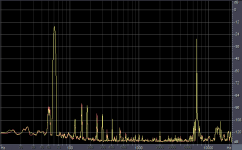
Here's an IMD measurement, 60Hz + 7kHz, 4:1, 8V-pk output. Red is my circuit, yellow an NE5534. The traces overlay almost exactly, leading me to believe that the IMD and HD is mostly from the measurement equipment itself, also the 50Hz + harmonics.
Attachments
Hi all,
Has the circuit been tried with other transistors? How sensitive is it to variations (i.e. beta mismatch, altogether different set of transistors)? Looks very interesting to try out...
I'm curious as to what equipment is being used to characterize the circuits and generate the plots - I seem to pick up that its a sound card on a computer - is that a commercially available "system" - i.e. sound card + test box + sw? If so, what?
Many thanks!
- Status
- This old topic is closed. If you want to reopen this topic, contact a moderator using the "Report Post" button.
- Home
- Amplifiers
- Solid State
- Improved discrete op-amp