
Add a pair of 47µF 100V bypass caps to the main filter cans.
If your cards only have one trim pot you will need to add a pair of 0.1µF film caps per channel. One to bypass the input coupling cap, and one for the feedback loop cap.
The above gives the biggest gain for the time and money invested. Further gain becomes expensive in both time and money.
The power cord is a 16ga type used on 1.8KW space heaters, it is adequate.
djk said:Add a pair of 47µF 100V bypass caps to the main filter cans.
If your cards only have one trim pot you will need to add a pair of 0.1µF film caps per channel. One to bypass the input coupling cap, and one for the feedback loop cap.
The above gives the biggest gain for the time and money invested. Further gain becomes expensive in both time and money.
The power cord is a 16ga type used on 1.8KW space heaters, it is adequate.
Hi djk,
Do you add the 47uf caps directly across the terminals of the caps themselves?
Thanks, Terry
I usually add four solder lugs with internal teeth on top of the existing lugs.
I also make a 1/16" thick 3/8" wide copper buss bar to replace the 16ga wire for the ground. I drill three 1/16" holes at the midpoint for the transformer center tap, speaker grounds, and signal ground.
I also make a 1/16" thick 3/8" wide copper buss bar to replace the 16ga wire for the ground. I drill three 1/16" holes at the midpoint for the transformer center tap, speaker grounds, and signal ground.
djk said:Add a pair of 47µF 100V bypass caps to the main filter cans.
.
djk,
Would it be any good to bypass with 1000uF, then 100uF or 47uF then 0.1uF? (I have many 1000uF's lying around)
djk said:I usually add four solder lugs with internal teeth on top of the existing lugs.
I also make a 1/16" thick 3/8" wide copper buss bar to replace the 16ga wire for the ground. I drill three 1/16" holes at the midpoint for the transformer center tap, speaker grounds, and signal ground.
OK, it sounds like you are adding a type of star ground to the filter caps. I still don't understand where you are attaching the 47uf by-pass caps.
Thanks, Terry
Hafler DH upgrades
Hi newfinish
I suggest that you read this thread since the DH-500 uses the same driver board as the DH-220 (PC-19C card). It is also very similar to the DH-200 (PC-6 card).
http://www.diyaudio.com/forums/showthread.php?postid=359323#post359323
There are plenty of stuff to do out there....
The power supply upgrade is always a good start.
Good luck
"OK, it sounds like you are adding a type of star ground to the filter caps. "
It already has a star ground, but it is a piece of 16ga wire. If you drive a 2 ohm load in stereo, the peak current in this wire is on the order of 80A. The huge copper buss bar works better.
" I still don't understand where you are attaching the 47uf by-pass caps."
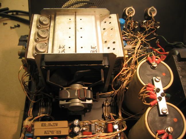
Kind of hard to figure out "I usually add four solder lugs with internal teeth on top of the existing lugs. "? There is only one place in the amplifier with four solder lugs. Look at the main filter caps.
"oooook! you kinda lost me there have a diagram or some thing to help?"
You can download the manuals from Hafler for free, but if you can't find the main filter caps maybe you shouldn't be inside the amplifier anyway. If you follow the wire from the input jacks you will find the input coupling caps. The feedback caps are the only cap around 220µF~470µF on the boards.
http://www.hafler.com/techsupport/index.asp?ID=3#amplifiers
"what twill all that do to help?"
Clearer mids and highs, better detail and imaging, tighter bass.
"Would it be any good to bypass with 1000uF, then 100uF or 47uF then 0.1uF? (I have many 1000uF's lying around) "
That would be OK, but the 0.1µF needs to be bigger, more like 0.47µF~1µF. This may cause the amplifier to oscillate. If it does, try adding about 5 ohms in series with this cap.
There are hundreds of things you can do for a Hafler amp, this is just the biggest bang for the buck (about $4 worth of caps).
It already has a star ground, but it is a piece of 16ga wire. If you drive a 2 ohm load in stereo, the peak current in this wire is on the order of 80A. The huge copper buss bar works better.
" I still don't understand where you are attaching the 47uf by-pass caps."
Kind of hard to figure out "I usually add four solder lugs with internal teeth on top of the existing lugs. "? There is only one place in the amplifier with four solder lugs. Look at the main filter caps.
"oooook! you kinda lost me there have a diagram or some thing to help?"
You can download the manuals from Hafler for free, but if you can't find the main filter caps maybe you shouldn't be inside the amplifier anyway. If you follow the wire from the input jacks you will find the input coupling caps. The feedback caps are the only cap around 220µF~470µF on the boards.
http://www.hafler.com/techsupport/index.asp?ID=3#amplifiers
"what twill all that do to help?"
Clearer mids and highs, better detail and imaging, tighter bass.
"Would it be any good to bypass with 1000uF, then 100uF or 47uF then 0.1uF? (I have many 1000uF's lying around) "
That would be OK, but the 0.1µF needs to be bigger, more like 0.47µF~1µF. This may cause the amplifier to oscillate. If it does, try adding about 5 ohms in series with this cap.
There are hundreds of things you can do for a Hafler amp, this is just the biggest bang for the buck (about $4 worth of caps).
djk said:[B
"Would it be any good to bypass with 1000uF, then 100uF or 47uF then 0.1uF? (I have many 1000uF's lying around) "
That would be OK, but the 0.1µF needs to be bigger, more like 0.47µF~1µF. This may cause the amplifier to oscillate. If it does, try adding about 5 ohms in series with this cap.
[/B]
This was helpful info. Is this oscillation (with the 0.1uF) more an issue with the Hafler or would it be an issue with a 555?
thanks!
" I still don't understand where you are attaching the 47uf by-pass caps."
Kind of hard to figure out "I usually add four solder lugs with internal teeth on top of the existing lugs. "? There is only one place in the amplifier with four solder lugs. Look at the main filter caps.
Are you being sarcastic? Was my question not clear?
How does your telling me that you add four solder lugs on top of the existing lugs tell me where the leads for the new caps attach?
OK, mine is a P500, so maybe it looks different but I don't see any solder lugs on the filter caps.
Let me ask in a different way. Do you wire the 47uf caps in parallel with the filter caps?
Thanks, Terry
still4given said:
Do you wire the 47uf caps in parallel with the filter caps?
Thanks, Terry
Yes Terry, if you did them in series, you total amplifier capacitance would be about 44uF...

george a said:rgulate the PS t the frnt end alone will prob make a huge difference, it did for my dh-200..
cheers
I completely agree !
"rgulate the PS t the frnt end alone will prob make a huge difference, it did for my dh-200..
cheers"
I agree, but it is quite a project for many.
http://www.audioxpress.com/bksprods/pcbs/nelsonpass.htm
ITEM # PCBP-10B Pass/Thagard A75 Power Amplifier
From Audio Amateur Issues 4/92 and 1/93. Pass/Thagard A75 2-channel power amplifier power supply board. 3-3/8 " x 5". 1 lb. $8.95
http://www.passdiy.com/pdf/a75p2.pdf
djk said:"rgulate the PS t the frnt end alone will prob make a huge difference, it did for my dh-200..
cheers"
I agree, but it is quite a project for many.
http://www.audioxpress.com/bksprods/pcbs/nelsonpass.htm
ITEM # PCBP-10B Pass/Thagard A75 Power Amplifier
From Audio Amateur Issues 4/92 and 1/93. Pass/Thagard A75 2-channel power amplifier power supply board. 3-3/8 " x 5". 1 lb. $8.95
http://www.passdiy.com/pdf/a75p2.pdf
Djk,
Will the main board work with 90v rails or just use the OSU?
djk said:"rgulate the PS t the frnt end alone will prob make a huge difference, it did for my dh-200..
cheers"
I agree, but it is quite a project for many.
http://www.audioxpress.com/bksprods/pcbs/nelsonpass.htm
ITEM # PCBP-10B Pass/Thagard A75 Power Amplifier
From Audio Amateur Issues 4/92 and 1/93. Pass/Thagard A75 2-channel power amplifier power supply board. 3-3/8 " x 5". 1 lb. $8.95
http://www.passdiy.com/pdf/a75p2.pdf
The PASS is quite a good circuit but may be too big to fit in some amp cases. The use of IC regulators is also a good compromise for performance/complexity ratio.
Briefly looking at the schematics for a DH 500, I believe the removal of D11, D12, D13 and D14 would improve transient response at the expense of over voltage protection but it should make a significant imoprovement.
Also changing the bridge DB401 to soft recovery diodes might soften the amps sound. Not sure but no danger here.
DON'T remove the fan.
Additionally removing the output relay would definitely reduce output impeadance and therefore increase the damping characteristics. But you would need to build some protection in at the power supply and beware that this relay suorts the caps when powered down. Without the relay the caps will drain very slowly.
There is a 100 uf bypass on the board thogh this is electrolytic and therefore could be improved.
Finally the output speaker fuses should be bypassed not high end equipement would dare this in the signal path.
Changes should be made one at a time. So that problems can be more easily resolved.
Let me know what you think
Take care
- Status
- This old topic is closed. If you want to reopen this topic, contact a moderator using the "Report Post" button.
- Home
- Amplifiers
- Solid State
- hafler 500 upgrades...