
Hi,
C11 & C12 OK in new position.
A small refinement for you to think about; use separate decoupling for the Hi current end beside the output transistors ie. to the right of the fuses by adding 100nF in// with C11 & C12. Then add electrolytic to Lo current side of the supply by adding 100uF beside the 47nF.
Hi AndrewT!
I put the capacitors like You said.
In documentation of this amp I read that
I can only put a load of 8ohms and I will
get about 60W RMS.
Can I add more outputs (like I do it on my scheme)
so I can have a load of 4ohms?
Do I need something else in my scheme
if I want to do that?
Thanks everybody!
http://xthost.info/bonus/multiplier1.jpg
Hi,
I do not know the IRF devices, but I think 1 pair could drive any 8ohm load and a resistive 4ohm load.
To drive a severe 4ohm load I think you need to double up on the IRFs and the source resistors. You should aim to test you amp for stability into a resistive load about half of your speaker impedance. i.e. you need to check the amp into 2ohm resistive.
Your schematic shows the IRFs driven straight off the BF470, what is their current capacity at the voltage and temperature you will run them at? You may need to add a pair of drivers to cope with the doubled current into the IRFs.
OK, a few pointers:
The 100uF caps in parallel with 47nF on the driver side power supply need to be larger to create a large enough time constant so that you get no real power line droop even at the lowest bass notes. Use 220-470uF.
Trimmer in the Vgs multiplier needs pins 3 and 2 connected together or the Vgs multiplier will be very touchy to adjust and potentially problematic should the pot have problems with the wiper (even if it is driving a MOSFET gate).
Driver stage has (approximately) 10mA of current availabe to drive the MOSFETs. This should be adequate for one pair of IRFP240/9240. BTW for power rails below +-45 use IRFP240/9140, over +-45 and up to +-90 use IRFP340/9240 for best P/N complementarity.
Regarding power, given proper cooling a single pair of 9240/240 should work into decent behaving 4 ohm speakers at unloaded 40V rails, but it's right at the edge. The 9240 is the weak link here with 11A max Id, and 150W max Pdiss, but this is still better than 7A and 100W of the original transistors.
Paralleling devices is possible but not exactly trivial. You could do it as in your schematic, but it would be prudent to increase the resistors in the sources from 0.22 ohm to 0.33 or even 0.39, unless you also pre-select the transistors for Vgs (which would require you to buy lots more than you need). The problem with this approach is that you get more losses on the resistors at full power.
Also, you may need to correct the valuse of the gate protection zeners. In general, you need about 5.5V to turn the IRFPs fully on at typical temperatures, and you need to account for the voltage drop on the source resistors at full power. A 10A ball-park figure for 4 ohms resistive is OK for the current through the MOSFETs, so for single pair 0.22 ohm Rs you need to plan for about 8V drop across zener + diode that is between the gate of the power MOSFET and output. For two pairs, keep in mind that you have about half the current going through each transistor, so two pairs with Rs = 0.39 ohms actually comes out almost the same. Keep in mind that with two pairs of transistors, you get ~~2x total bias current as it has to stay more or less the same PER PAIR.
In order to drive the output stage properly when there are two output pairs, you will need to either increase the driver stage current, or add a buffer stage. I would go with the first as it only makes more heat, unlike the second that adds one more stage and possible instability. Strangely enough, it is easyest to increase the driver stage current by increasing the first stage tail current. The first stage is actually run quite low. Reducing the value of R7 to 2.7k will approximately double all currents. It will also increase DC offset at the output 2x, as well as the input resistor noise contribution. If it gets excessive, you can slightly alter the value of R3 or R4 by paralleling a larger value resistor with one of them (only one!), say about 47k or more. Correcting R3 will move offset one way, R4, the other (+-).
I would concur about removing the large 15k at the input as it adds noise un-necessairly. That being said, it is probably an attempg to protect the input and create a pole with the input capacitance of the transistor. The same could be done just as adequately with a 2.2k resistor and cca. 330-560pF to ground after it, with far less noise.
Hi Ilimzn,
I have never checked the decoupling time constant before but your answer prompted me to look at some numbers.
Here's what I did, can you confirm if this is correct?
Driver and input stage current about 15mA
Effective impedance about 40V/0.015A = 2k66
RC time constant about 2k66 * 470uF = 1.25S
This value seems a bit high. Would 100uF giving 270mS provide sufficient decoupling?
AndrewT, your calculation is sufficiently accurate for a ballpark figure. In this particular amp, however, the capacitors discharge linearly because the current draw is constant (unless it's clipping), therefore faster discharge is observed, at a rate of I/C V/s, so about 32V/s for 470uF. Even if you look at it through a time constant view, RC gives you the time until the coltage on the cap falls to ~37% of original voltage at t=0. In either case, you want the voltage to be as constant as possible between cap replemishments through the diode.
You should remember that you need to look at the time constant in reference with the input signal ENVELOPE, not with the mains frequency, or even with input signal frequency (the latter not directly).
Mains carries ripple, at 100/120Hz, so you have a time of <= 10mS till the capacitors are normally replenished. For 470uF, the ripple would be only 0.32V, regarding the mains frequency recharge, with 100uF it would be 1.5V. Neither is particulary problematic, especially as it assumes no previous filtering, not true in this case. In actuality, at idle, the ripple can be disregarded in either case.
Things change a bit when you look at the fact you want about 8-10V or so more for the driver stage at full power. Assuming a 10V power supply droop (and that would actually be quite good), with an input signal at 20Hz, you need to take into account that the current drain caused by the output is HALF WAVE rectified 20Hz on the power line, hence you get ripple at 50ms periods in the power line, with spikes at 10ms as the rectifier is trying to replenish the main filter caps. In order to keep 10V over the droop, in theroy we vould require infinite capacitors, however, taking 50ms as a reference, the voltage on the 10uF cap would reduce by 7.2V, while with 470uF it would reduce by 1.6V. Again, this is assuming no extra filtering, which in this case is not true, but the example is indicative.
The situation can be even worse - when you look at input signal envelopes. If you want sustained maximum power, then this approach definitely does not work - you simply need a permanently higher supply for the driver stages (this is actually not so difficult to do and has other benefits). For music signals you really do not need to account for more than about 100ms or so of a 'peak', and because you DO have previous filtering via the main filter caps the voltage on the supply lines does not drop abruptly, there is a time constant involved. What it comes down to is providing capacitors for the driver stage that will keep the driver voltage as close to idle supply voltage, and at least 10V over the lowest 'dip' in the power line at full output during a transient, whichever is larger. Taking 470uF as an example, it produces a ~3V droop after 100mS assuming an abrupt drop in supply voltage, which would be adequate for a supply line doop of 13V at full power, not unreasonable for a typical power supply of a 60W amp. In reality, a transient longer than 100ms could be sustained relatively easily due to the action of the main filter caps.
One more thing: dimensioning the capacitors so that the power lines droop (develop ripple) at maximum power is very often used to limit thermal losses in output transistors during sustained maximum power operation, and especially during a fault condition. In essence, the main filter caps are dimensioned by the amount of energy they store - this should be signifficanty less than the output transistors can take, but signifficantly more than is needed to blow the fuses! This normally results in rather 'soft' power supplies, and the method I outlined is a way to mitigate that and retain maximum power during transients. During such transients the distortion will be somewhat higher but since the likelyhood of te amp clipping at the same time is high, it is a relatively samll price to pay for an amp that performs decently, with a moderatly sized power supply.
hi Ilimzn!
I've decided to stay on one pair of irf's for now
but I will put a larger heatsink for 4 ohms load..
btw. in which class work this amp now?
I saw in specifications that diodes D7 and D8(which i
removed)put SRT in AB class and with another 1n4148
diode in series this amp works practical in class A.
Which situation is now without this diodes?
And yes,Thank You for everything!")
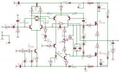
here is the final scheme if someone also want to build this amp!
http://xthost.info/mbonus/irf_amp.jpg
best regards,
bonus!
I've decided to stay on one pair of irf's for now
but I will put a larger heatsink for 4 ohms load..
btw. in which class work this amp now?
I saw in specifications that diodes D7 and D8(which i
removed)put SRT in AB class and with another 1n4148
diode in series this amp works practical in class A.
Which situation is now without this diodes?
And yes,Thank You for everything!
here is the final scheme if someone also want to build this amp!
http://xthost.info/mbonus/irf_amp.jpg
best regards,
bonus!
it's me again...
i finally finished this amp
and i had a small problem
when i tested my amp..
I didn't make original power supply yet
so i tested it on +/-12v 200VA (only this
i've found at my home..)
problem was that I heard a very small(but it's here)
buzz from the speaker and I don't know what is wrong.
The signal was from my soundcard so i thought this may
be the problem but when i put av400 on my soundcard,there
are no problem with buzz.
Is the power supply of +/-12v maybe a problem?
everything else works great. pretty clear and dynamic sound
except this buzz when i turn down the volume.. .
and another thing-it is very loud to me for this power supply.
(much louder then my old 18W hi-fi..)
is this ok?
thanks everybody!
schematic:
Attachments
The buzz (50Hz or 100Hz) is likely hum pickup from th emains line or the transformer stray field, and probably has to do with your wiring. People often assume that wires can be routed anywhere, but this is not true, though the subject where they should go, is quite complex if expressed as a set of do's and don'ts. The idea is to recognise the loops where current flows and understand that current through them will induce a magnetic field, as well as a magnetic field will induce current in them. To avoid this, areas described by the loop must be kept as small as possible, and of course, non-overlapping if we want no interaction. Secondly, things like ground lines DO have resistance and voltage drops - large currents through the ground will make potential differences on the ground wire, which may be picked up by amplifier inputs, feedback loops etc.
Regarding class of operation, in this amplifier it depends solely on the bias current of the output stage, so it's a matter of how you adjust it, given the required output into the given load. That being said, it is NOT the same what current you adjust. For one, increasing it, increases heat dissipation. At +-40V power supply, class A operation for a 4 ohm load would require idle current equal to maximum load current, about 8A, therefore 640W of heat dissipated, clearly well beyond what a pair of IRFPs can do, and indeed even if they could, the heatsink would be enormous (there is no escape from physics...). The same is true for the original design since it uses even lower rated transistors. Therefore, you can chose various settings in class AB. That being said, there is an 'optimum' idle current for the given load, but in the case of driving a speaker, which is a complex load, the value is mostly a compromise arrived at by lots of listening tests, and heat generation/reliability considerations.
Regarding class of operation, in this amplifier it depends solely on the bias current of the output stage, so it's a matter of how you adjust it, given the required output into the given load. That being said, it is NOT the same what current you adjust. For one, increasing it, increases heat dissipation. At +-40V power supply, class A operation for a 4 ohm load would require idle current equal to maximum load current, about 8A, therefore 640W of heat dissipated, clearly well beyond what a pair of IRFPs can do, and indeed even if they could, the heatsink would be enormous (there is no escape from physics...). The same is true for the original design since it uses even lower rated transistors. Therefore, you can chose various settings in class AB. That being said, there is an 'optimum' idle current for the given load, but in the case of driving a speaker, which is a complex load, the value is mostly a compromise arrived at by lots of listening tests, and heat generation/reliability considerations.
- Status
- This old topic is closed. If you want to reopen this topic, contact a moderator using the "Report Post" button.
- Home
- Amplifiers
- Solid State
- help!ab class mosfet amp