Hi,
Question - has anyone tried MJL 4281 at the output instead of the mj15003. I have hood amp 1996 version with ccs at the input and at the driver stage........ They are to246 devices and they are better suited for my heatsink.
Should anything be added arround them when replacing mj15003 with them?
best regards and thanks
You can use the MJL4281 (or MJL3281 or 2SC5200) in the JLH but you will almost certainly need to provide additional compensation and an output Zobel, to ensure stability into a variety of loads, due to the higher ft of these devices.
The Zobel (10R + 100nF) is no problem. The additional compensation (a small value capacitor between the the collector and base of Q3 or between the collector of Q3 and the emitter of Q4) will significantly reduce the open-loop bandwidth of the amp. IMO, one of the benefits of the JLH (without additional compensation) is that the open-loop bandwidth extends over virtually the full audio range so the amount of feedback does not decrease with rising frequency as it does in compensated amplifiers.
You may wish to consider the MJL21194 which is a slower (4MHz) power transistor in a TO-247 case.
dear sir,
thank You for Your kind reply.... which of the suggestions would be better for the hood amp version 1996 - i assume the mjl21194?.... also should I use any zobel and additional compensation if I use mjl21194??
Is this been tried and what are the sonic results?
thanks again and best regards
thank You for Your kind reply.... which of the suggestions would be better for the hood amp version 1996 - i assume the mjl21194?.... also should I use any zobel and additional compensation if I use mjl21194??
Is this been tried and what are the sonic results?
thanks again and best regards
MikeW has built the higher power version (parallel output transistors) of the JLH using the MJW21194 (the fully insulated version of the MJL21194) and has reported good results. I believe several people have used his pcb to make their amps and all have worked well. Additional compensation and a Zobel were not required with the 21194.
I would prefer slightly more gain than the MJL21194 offers but not at the expense of having to use additional compensation, as with the MJL3281 etc. Unfortunately, I have not been able to find a flat-pack device with an ft of around 4MHz and a gain greater than that of the 21194 without resorting to the likes of the TIP3055, when parallel pairs of output transistors would be needed for the 'standard' version and which has a far less linear gain v collector current.
I would prefer slightly more gain than the MJL21194 offers but not at the expense of having to use additional compensation, as with the MJL3281 etc. Unfortunately, I have not been able to find a flat-pack device with an ft of around 4MHz and a gain greater than that of the 21194 without resorting to the likes of the TIP3055, when parallel pairs of output transistors would be needed for the 'standard' version and which has a far less linear gain v collector current.
So - to conclude from the above..... it would be nice if I would cool my mj15003 to an reasonble level of temperature so I do not have to change them..... if I still have to change them (since they are now running at 80 degrees celsius) it would be good to use mjw or mjl 21194..... thanks for the reply - i would not like to take any of Your time......
best regards
best regards
You can use the MJL4281 (or MJL3281 or 2SC5200) in the JLH but you will almost certainly need to provide additional compensation and an output Zobel, to ensure stability into a variety of loads, due to the higher ft of these devices.
Why is this? I haven't seen a schematic of this amp lately, but the GBP of the amp is probably fixed by the earlier stages. Therefore, shouldn't adding faster outputs extend their poles even higher for less phase shift and therefore stability problems, since the unity gain frequency of the outputs will now be farther away from the open loop unity gain frequency?
It took a bit of digging, but I've found where MikeW posted his PCB layout:Geoff said:MikeW has built the higher power version (parallel output transistors) of the JLH using the MJW21194 (the fully insulated version of the MJL21194) and has reported good results. I believe several people have used his pcb to make their amps and all have worked well. Additional compensation and a Zobel were not required with the 21194.
http://www.diyaudio.com/forums/showthread.php?postid=432904#post432904
He suggests he will donate it for a group buy, which I would be interested in if there are others interested.
p.s. Geoff, your WWW button here seems to be set to your old website address.
paulb said:p.s. Geoff, your WWW button here seems to be set to your old website address.
Paul
Thanks for pointing that out. It was my error, I put .com instead of .co.uk (my ISP's address is .com for emails etc but .co.uk for websites. Confusing!). I am surprised that no one has pointed out the broken link previously. I must have had the wrong address in my profile for nearly two years now.
On the subject of pcbs, I have a design for the higher power version (which could also be used with only single output transistors) and an associated power supply. The prototypes should have been built by now and the results pubished on my website but the person building them has had to defer expenditure until after his family holidays next month.
When the boards have been proven, I intended to see if there was any interest in having them made commercially. The boards will be standard eurocard size (160 x 100) to accommodate decent sized heatsinks for Q3 and Q8, terminal blocks for all connections to/from the boards etc. The power supply board will allow for on-board D-220 rectifier diodes, on- or off-board reservoir capacitors and either a 'follower' regulator (TL431 or Zener reference) or a capacitance multiplier.
The commercial boards will probably be double sided PTH since here in the UK these can be obtained in small quantities at a lower price than single sided, but I have arranged the layout so that anyone who wishes to etch thier own single sided boards can do so (there is only a single link on the upper side of each board).
Geoff
pooge said:
Why is this? I haven't seen a schematic of this amp lately, but the GBP of the amp is probably fixed by the earlier stages. Therefore, shouldn't adding faster outputs extend their poles even higher for less phase shift and therefore stability problems, since the unity gain frequency of the outputs will now be farther away from the open loop unity gain frequency?
A good question! Simulation indicates that the gain/phase margin is significantly reduced when high ft (eg 2SC5200, MJL3281 etc) power transistors are used and this has been borne out in practice with amps oscillating merrily with the more modern devices.
I know of only one person who has not needed additional compensation when using the high ft power transistors and this was in a standard 1969 version where I suspect the reduced effectiveness of the bootstrap arrangement at high frequencies caused the open-loop gain to roll-off earlier. Others have had problems with these transistors even in the 1969 version so I also suspect that the stability is marginal and layout dependant.
I don't see it being that hard to use the higher gain/ft transistors.
If they oscillate, just put a small cap over the B-C leads of the drivers with a low value base resistor.
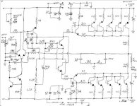
This amp I built using 230W MJL4281/4302 is for a subwoofer, but this amp also delivers excellent treble response as well. I went TO-247 types because of their high power handling, ease of mounting, and that because they are so large, they work better with the heatsink.
I also have some 200W MJL21195/96 transistors but I didn't use them because the gain is lower and also have more gain droop than the 4281/4302. Also I used 5 pairs of output transistors (overkill ) to reduce gain droop and reduce individual transistor temps to that the total heat made is spread better along the heatsink.
If you don't wanna use the 4281, then use another transistor such as the 21196 or comparable flat transistor that can handle the wattage you need.
If they oscillate, just put a small cap over the B-C leads of the drivers with a low value base resistor.
This amp I built using 230W MJL4281/4302 is for a subwoofer, but this amp also delivers excellent treble response as well. I went TO-247 types because of their high power handling, ease of mounting, and that because they are so large, they work better with the heatsink.
I also have some 200W MJL21195/96 transistors but I didn't use them because the gain is lower and also have more gain droop than the 4281/4302. Also I used 5 pairs of output transistors (overkill
) to reduce gain droop and reduce individual transistor temps to that the total heat made is spread better along the heatsink.If you don't wanna use the 4281, then use another transistor such as the 21196 or comparable flat transistor that can handle the wattage you need.
Attachments
EWorkshop1708 said:I don't see it being that hard to use the higher gain/ft transistors.
If they oscillate, just put a small cap over the B-C leads of the drivers with a low value base resistor.
It isn't, but see my previous post (#2) regarding the reduction in open-loop bandwidth.
The JLH does not use driver transistors so you cannot put a capacitor across them.
Hi Geoff,Geoff said:On the subject of pcbs, I have a design for the higher power version (which could also be used with only single output transistors) and an associated power supply. The prototypes should have been built by now and the results pubished on my website but the person building them has had to defer expenditure until after his family holidays next month.
When the boards have been proven, I intended to see if there was any interest in having them made commercially. The boards will be standard eurocard size (160 x 100) to accommodate decent sized heatsinks for Q3 and Q8, terminal blocks for all connections to/from the boards etc. The power supply board will allow for on-board D-220 rectifier diodes, on- or off-board reservoir capacitors and either a 'follower' regulator (TL431 or Zener reference) or a capacitance multiplier.
The commercial boards will probably be double sided PTH since here in the UK these can be obtained in small quantities at a lower price than single sided, but I have arranged the layout so that anyone who wishes to etch thier own single sided boards can do so (there is only a single link on the upper side of each board).
Geoff
I am interested and looking forward to seeing your layout (now I won't bother with my own). It may not be cost-effective for me to order UK boards, as the exchange rate is a killer, but I could perhaps etch a single-sided board. Alternatively, I could arrange a group buy here if the pricing looks favorable.
wow
lots of replies....... thanks guys ...... it seems that I would stay with mj15003 after all...... I have determined that I would better be using mica pads under mj's instead of silicon and also a very good thermal greese. On other thread that I was asking in paralel with this one - it was about to hot mj15003's - they clearly noted that silicon is not beter than mica insulating pads..... So I might cool my output transistors after all. If not I still have this option to do 
thanks for Your time and effort......

I meen MikeW version with MJW21194 and without zobel and anything..... and with one output pair .... and optimized Iq current and sch....
lots of replies....... thanks guys ...... it seems that I would stay with mj15003 after all...... I have determined that I would better be using mica pads under mj's instead of silicon and also a very good thermal greese. On other thread that I was asking in paralel with this one - it was about to hot mj15003's - they clearly noted that silicon is not beter than mica insulating pads..... So I might cool my output transistors after all. If not I still have this option to do
thanks for Your time and effort......
I meen MikeW version with MJW21194 and without zobel and anything..... and with one output pair .... and optimized Iq current and sch....
pooge said:Perhaps some small value base stopper resistors in the output devices could help prevent oscillations.
maybe - but if mjw21194 is o.k. of anything than this one will be my favorite....
- Status
- This old topic is closed. If you want to reopen this topic, contact a moderator using the "Report Post" button.
- Home
- Amplifiers
- Solid State
- MJL 4281 in hood amp - 1996 version with ccs