I have built a Quad 405 amp recently and have ironed out most of its problems thanks to people in these threads, thankyou.
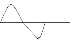
I have one more issue left with my amp and that is triangulation of negative cycles at higher frequencies above 10Khz and when more power is drawn from the amplifier (e.g. higher wattage output and lower impedance load).
The triangulation becomes steadily worse as frequency increases and looks like a triangle wave with crossover distortion when made to look worst.
I cannot find a flaw in my circuit wiring and am using transistors that have been tried and tested to work in this amplifier.
What is this that i am seeing and what causes it?
I am on the verge of pulling out my PCB's and building a different amplifier in a few months time maybe, this Quad is driving me nuts

Cheers
Craig
I have one more issue left with my amp and that is triangulation of negative cycles at higher frequencies above 10Khz and when more power is drawn from the amplifier (e.g. higher wattage output and lower impedance load).
The triangulation becomes steadily worse as frequency increases and looks like a triangle wave with crossover distortion when made to look worst.
I cannot find a flaw in my circuit wiring and am using transistors that have been tried and tested to work in this amplifier.
What is this that i am seeing and what causes it?
I am on the verge of pulling out my PCB's and building a different amplifier in a few months time maybe, this Quad is driving me nuts
Cheers
Craig
Attachments
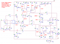
Thanks for your replys, i will post the schematic to help. I have measured the signal of the base of Q1 2N5551 and its fine, from then on the signal looks unrecognisable until the collector of Q5 where it appears ok but exibits the problem.
What voltages would you expect on each diode in this circuit, i was a little concerned to only get 0.33V at D1 anode, 20mV at D2's and 3mV at D3's.
I measured -0.6V at Q4's base too which seems fine.
P.S. I have added the voltage measurements, maybe you can spot a glaring error with them? supply is actually about 56.5V
Cheers
Craig
Attachments
The 22uH inductor i think provides some high frequency attenuation, i guess it helps to prevent oscillations, forcing them through the 15 ohm resistor.
The 'feedback' from the other inductor 3.3uH is actually feedforward .
This amplifier is 2 amplifiers in one, the class A stage with the BD244's controls the output totally until the current through the 47ohm resistor exceeds about 40mA i think, then the power dumping transistors kick in to provide all the meaty current for the rest of the cycle.
The result is supposed to eliminate crossover distortion by keeping the output swing class A but allow a more effiecient class C power amplifier to deliver all the power.
Cheers
Craig
The 'feedback' from the other inductor 3.3uH is actually feedforward
.This amplifier is 2 amplifiers in one, the class A stage with the BD244's controls the output totally until the current through the 47ohm resistor exceeds about 40mA i think, then the power dumping transistors kick in to provide all the meaty current for the rest of the cycle.
The result is supposed to eliminate crossover distortion by keeping the output swing class A but allow a more effiecient class C power amplifier to deliver all the power.
Cheers
Craig
Please note that the QUAD 405 is a Current Dumping amplifier ;-)
You can find the original schematic here:
http://www.audio-circuit.dk/Schematics/QUAD 405 Schematic.pdf
You can find the original schematic here:
http://www.audio-circuit.dk/Schematics/QUAD 405 Schematic.pdf
- Status
- This old topic is closed. If you want to reopen this topic, contact a moderator using the "Report Post" button.
- Home
- Amplifiers
- Solid State
- Triangulation