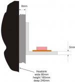
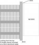
picture from the top of the heatsink..... the problem is bad airflow perhaps - because of the small heatsinks - they have their radiators in the wrong direction (the don't go from the side plate to left and right but they go along the side plate of the housing)..... Also, probably - i have that aditional 8mm alu- plate that represents aditional thermal resistance.... I will try to put small heatsins on the top of every mj15003 to aditionally cool them also.... maybe this would work to turn the temperature down.....
Attachments
I would say that that plate you have sandwiched between th L shaped metal and the heatsink probably doesnt help.
The more gaps you have to bridge using heat sink compound the more thermal resistance you get, and if your transistors are much hotter than your heatsink then their is definatly a thermal resistance issue.
They should be of a much closer temperature if well mounted.
Craig
The more gaps you have to bridge using heat sink compound the more thermal resistance you get, and if your transistors are much hotter than your heatsink then their is definatly a thermal resistance issue.
They should be of a much closer temperature if well mounted.
Craig
Craig405 said:I would say that that plate you have sandwiched between th L shaped metal and the heatsink probably doesnt help.
The more gaps you have to bridge using heat sink compound the more thermal resistance you get, and if your transistors are much hotter than your heatsink then their is definatly a thermal resistance issue.
They should be of a much closer temperature if well mounted.
Craig
 I know, I know- but that plate is holding my heatsink together - I could only put other transistors like some to247 types or something - but I have allready buyed mj15003......
 I would try to put some heatsinks on the mj15003. Maybe that will help...
It's too hot if you can't hold your fingers on it!
IMO TO3 transistors are durable and reliable, but hard to put on heatsinks. I've done the L-bracket thing before, and the heatsink will be only warm, while the bracket and transistors are scalding hot.
MJL 4281/4302 are 230W Transistors TO-247. They are easy to mount compared to TO3, and handle nearly as much power.
EWorkshop1708 said:It's too hot if you can't hold your fingers on it!
thats what i thought..... i must think of something
btw... thnx for the tip regarding mjl**** --do You know, maybe, how do they sound in hood amp??


You need to reduce the losses at your junctions...ideally you would have the surfaces where they meet machined so that they make as perfect contact as possible, and use heatsink grease at those junctions.
At a minimum, you need to sand the surfaces as best you can, and use heatsink grease, and a slew of bolts to hold the assemblies firmly together (drilled and tapped holes to bolt everything together also need to be ever-so-slightly countersunk to account for the rise in the material caused by drilling the holes).
At a minimum, you need to sand the surfaces as best you can, and use heatsink grease, and a slew of bolts to hold the assemblies firmly together (drilled and tapped holes to bolt everything together also need to be ever-so-slightly countersunk to account for the rise in the material caused by drilling the holes).
EchoWars said:You need to reduce the losses at your junctions...ideally you would have the surfaces where they meet machined so that they make as perfect contact as possible, and use heatsink grease at those junctions.
At a minimum, you need to sand the surfaces as best you can, and use heatsink grease, and a slew of bolts to hold the assemblies firmly together (drilled and tapped holes to bolt everything together also need to be ever-so-slightly countersunk to account for the rise in the material caused by drilling the holes).
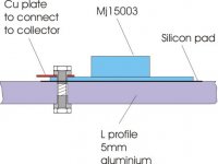
Here is how I have made it..... everything is o.k. and connected very good with silicon pads between the trans and the L profile
Attachments
sunrise said:
Here is how I have made it..... everything is o.k. and connected very good with silicon pads between the trans and the L profile
Just a SINGLE bolt? I really hope that you have been lazy in draving, not drilling
BTW. Silicone pads are sub-optimal compared to mica&thermal grease.
For really badly machined surfaces I recommended something like Arctic silver, available from computer stores. heat conductivity is at least 10 times better than ordinary heat transfer compound. And so is price.
Big single cut file is good in straightening aluminium pieces, but you need some practice with that. Sanding rounds off edges too easily.
mzzj said:
Just a SINGLE bolt? I really hope that you have been lazy in draving, not drilling
BTW. Silicone pads are sub-optimal compared to mica&thermal grease.
lazy in draving, laaazy in drawing - sorry.... so if I am understand it right - You recomend using mica transparent pads and thermal grease - tell me that this will help a little bit --- jessus, I have asked the guy is he 100% sure that silicon is better---- he said yeeeeesss - of course - like I am an idiot or something..... 
i have ceramique arctic silver and could put it with the mica transparent pads....
sunrise said:I will try to explain.... My mj15003 are connected to the 5mm aluminium L profile. That profile is connected to the 8mm 330x150mm aluminium plate that hold 12 small heatsinks together as one heatsink. picture attached
Calculate the thermal drop along the 5mm plate.
The equation for thermal resistance Case to Sink is: (sorry, I'm using inches)
Units: K is watts/(inch times C)
For aluminum, this number is 5.3, for copper, it is 10.2.
Length is in inches
Area is in inches times inches..
For your setup, assume a 45 degree spread, one inch from die to sink, .2 inch plate thickness.
The 45 spread opens to 1 inch at the sink, the average is .5 inch width.
So, your calculation is based on a structure that is:
1 inch long, .2 inches thick, and half inch effective width..
So, the calculation is: Theta C-S = 1 inch / (.2 inch times .5 inch times 5.3 W/inch C.
theta C-S = 1/(.2 * .5 * 5.3) degrees C per watt
Theta C-S =1.88 degrees C per watt.
This is the difference between your heatsink mount to the TO case. If you are dissipating 10 watts in the zistor, you are almost 20 degrees above the heatsink..
Yes, it's a model, and is not as exacting as one would like, but it shows how effective the plate really is for heat extraction..
Cheers, John..
Sunrise
Use 2 bolts to secure the MJ15003. With only one, the transistor is lifted on the other end, so almost no contact with bracket.
Correctly mounted, you will get about 10 deg centigrade difference between MJ15003 case and bracket, assuming bracket is normal alloy extrusions meant for fittings and not heatsink alloy.
Waste of time, thermal resistance to top of to-3 is huge compared to even worst L-bracket, there is maybe 0.2mm wall thickess for 5-8mm distance. And TO3 packages are made of steel, invar or something similar lousy conductor(well, some of them are aluminum but I think aluminum cases are more thing from past.)sunrise said:
I would try to put some heatsinks on the mj15003. Maybe that will help...
You should minimize distance from TO-3 case centerpoint to heatsink, as shown earlier in this thread thermal resistance of your L-bracket is quite high. Copper would be definetely better material but availlability at your local stores might be a problem.
80C case temperature is still okish in my mind, especially if thermal cycling is minimized. In my limited experience many of TO3 failures are thermal cycling related, after enough many cooling-heating cycles bonding wires separate from die. I have hacksawed some of failed TO3 out of curiousity, single over-current pulse results usually melted bonding wires, overtemperature results leaky or shorted transistor(with possibly blown off bonding wires or die as a result) and transistors with bonding wires separated from die are usually due to thermal cycling or vibration.
1.5A and 22V per transistor or is there more of them parallei? that would be around 35W and thermal resistance between junction and to3 case is 0.7C/W so junction temperatures would be 110C at junction. Maximum junction temperature is specified as 175C but this is more like "absolute maximum where device lifetime is equal to zero"
mzzj said:
1.5A and 22V per transistor or is there more of them parallei? that would be around 35W and thermal resistance between junction and to3 case is 0.7C/W so junction temperatures would be 110C at junction. Maximum junction temperature is specified as 175C but this is more like "absolute maximum where device lifetime is equal to zero"
mcp look at the post 12 - i was lazy in drawing -
didn't know that this will cause confuse..... mzzj 1.5A and +22V / 0V / -22V for one pair of transistors per ch. The sch is attahed... about that junction temperature - jlh original goes to Iq=2A , 22V. And it works...
I guess this must be o.k. (oh, it works with 2n3055 that is lower power trans. than mj15003).Attachments
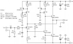

well it is not my circuit - it is a modification of 1996 jl hood amp made by mr. geoff moss (thanks) and mr. (I think his nick here is TimA).....
I have Onix OA601 power amplifier - very good unit indeed and I am powering it with a line preamp made around 12B4A. Rest of the system is Rogers Ls2a/2, Oelbach speakers cables, Pioneer 355 dvd as a transport and diy tda1543 dac; interconects are Siltech st-gt48 g3. I didn't realize how good the sound in my room can go until hood was placed there. And it is hood with no special parts, 250VA transformer, and 2 big cans for filtering. Nothing special (o.k. a have replaced my 2n3055 for mj15003)..... It sound simply great....... I have a whole lot of sound now and I have thought that my system was working again (it stopped after I have sold my Sonus Faber Minima Amator ). Onix sounds a little like dry. Hood is simply full with sound. It has still work to do on it- better parts, resolve the problem of heatsinking, etc. But in general it is very good sound for the money. Very good indeed.
Also, if You consider a new amp - try to look at this thread....
http://www.diyaudio.com/forums/showthread.php?s=&threadid=60546
maybe this would be even better.......
I have Onix OA601 power amplifier - very good unit indeed and I am powering it with a line preamp made around 12B4A. Rest of the system is Rogers Ls2a/2, Oelbach speakers cables, Pioneer 355 dvd as a transport and diy tda1543 dac; interconects are Siltech st-gt48 g3. I didn't realize how good the sound in my room can go until hood was placed there. And it is hood with no special parts, 250VA transformer, and 2 big cans for filtering. Nothing special (o.k. a have replaced my 2n3055 for mj15003)..... It sound simply great....... I have a whole lot of sound now and I have thought that my system was working again (it stopped after I have sold my Sonus Faber Minima Amator
). Onix sounds a little like dry. Hood is simply full with sound. It has still work to do on it- better parts, resolve the problem of heatsinking, etc. But in general it is very good sound for the money. Very good indeed.Also, if You consider a new amp - try to look at this thread....
http://www.diyaudio.com/forums/showthread.php?s=&threadid=60546
maybe this would be even better.......
- Status
- This old topic is closed. If you want to reopen this topic, contact a moderator using the "Report Post" button.
- Home
- Amplifiers
- Solid State
- mj15003 running at 80 degrees