Hi X.G.
Didn't get the chance to post this yesterday.
Thanks for your feedback, I'd love to see the circuit - can you show a copy ?
I have seen class-AB + CCS before, and I have seen claims that it maintains class-A operation.
To me all it does is maintain class-A in one half and offset the zero current class-AB crossover for the other, though such an arrangement can work better when the load is a *resistor*.
Here I have a separately active class-A device helping error correction at all times, and particularly during class-AB crossover at whatever voltage the loudspeaker might induce a class-AB current crossover. The lower class-A device is constantly working with the upper output half in the same manner that a JLH class-A amplifier operates.
I also retain JLH class-A bandwidth and low output inductance.
Cheers ....... Graham.
Hi Graham,
Congradulations on a very interesting design.
Could you perhaps kindly highlight the advantages (or perhaps disadvantages) of this design compared to JLH Class A (Geoff's latest update), upon which it is apparently based ?
One obvious aspect is power, but one could presumably build a high-power bridged version of the JLH using say a total of 8 output devices. This would also give close to a 100W ??.
Thanks,
Patrick
OH CARLOS !!!
Straight to 54 volts is a big jump.
My experience of bipolars has shown that every time you make a jump in rail voltage you *must* re-examine stability because the device characteristics change too.
You know I always use 22 ohms per rail to check before applying full power, well even then I still use 0.22 ohm 2.5 to 5W wirewounds until I am completely sure. Sometimes these will smoke/smell to warn of a high current draw that might not be enough to blow a fuse. Also, I always keep an AM radio beside a new amplifier and listen for oscillation at start-up. All you should hear is mains bourne interference and the diodes rectifying.
Very sorry to hear about this Carlos. Which position transistors blew, or did they all go ?
Once oscillation sets in NFB controlled drivers can cross-conduct output devices to destruction. I also wonder why you had to alter the feedback ratio - the gain should not have altered, had it been oscillating from the start ?
The quiescent currents do not need to be increased, 1A was rather a lot.
I need a cuppa before I go through this biasing stuff.
Hi Greg and Euvl,
Will be back shortly.
Cheers .......... Graham.
Already received the Sankens from my friend...mail here is wonderfull, and will go to
37 volts, as things are stable there...guaranteed stable using this voltage.
So, forget those dead Sankens...i am making efforce to fogive myself because of that.... stupid i was.
But now, a friend re-arranged the things to me, and another GEM will born next week
This weekend my birthday, so i will be around young girls in the beach and will have fun shopping...and eating as a thin dog!
Next week will have GEM, this time a pretty assemble...decent wiring, as it will be done to stay...from now to ethernity..will go to my son and to my grandson....hehe, near future the amplifier will be inside some watch...and speaker will be electrodes touching skin and transfering direct to brain.
I am afraid my grandson will use the aluminoum block to hold the door openned when we have strong wind days here...very common here strong winds.
Destiny is very bad when we go turning old..hehe...really bad.
Well, more two generations, if my grandson have one enemie... when young, can put the aluminium block inside one football ball...and ask the enemie to give a pretty good kick in that ball...for future they will find use for now a days amplifiers.
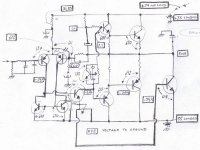
I will post some informs, a simple sketch, not pretty, but really informative... big utility to the ones decide to produce this lovely amplifier.
regards,
Carlos
37 volts, as things are stable there...guaranteed stable using this voltage.
So, forget those dead Sankens...i am making efforce to fogive myself because of that.... stupid i was.
But now, a friend re-arranged the things to me, and another GEM will born next week
This weekend my birthday, so i will be around young girls in the beach and will have fun shopping...and eating as a thin dog!
Next week will have GEM, this time a pretty assemble...decent wiring, as it will be done to stay...from now to ethernity..will go to my son and to my grandson....hehe, near future the amplifier will be inside some watch...and speaker will be electrodes touching skin and transfering direct to brain.
I am afraid my grandson will use the aluminoum block to hold the door openned when we have strong wind days here...very common here strong winds.
Destiny is very bad when we go turning old..hehe...really bad.
Well, more two generations, if my grandson have one enemie... when young, can put the aluminium block inside one football ball...and ask the enemie to give a pretty good kick in that ball...for future they will find use for now a days amplifiers.
I will post some informs, a simple sketch, not pretty, but really informative... big utility to the ones decide to produce this lovely amplifier.
regards,
Carlos
Attachments
Here is the board ready, in stand by mode, ready to go!
Parts are ready too, all them tested.
So, will construct monday morning.
Will be listening 9 AM, monday, next week
Will have my Birthday watching "60 seconds" movie... "Eleonora" the car, the Mustang...the most wide world pretty automobile.
700 Horsepower and 300 watts of sound in my room...4 AKSAS and one strong Symassym.
regards
Carlos
Attachments
Hi Carlos,
_________________________________________
Bias adjustment.
I initially said link out the class-AB bias pot and set up the 400mA class-A quiescent. Then remove link and add 100mA class-AB bias.
Next I suggested it would be okay to set the AB bias preset at 50% before switch-on, then set 400mA class-AB bias, then the 100mA class-AB. No link would be needed using this method.
Either method is suitable.
__________________________________________
For the first power-up I start with 22 ohm seies power rail resistors and no load. Don't set the bias but check check for unusual heat and the output terminal being at zero, probably within a few millivolts.
Next I remove 22 ohm and insert the 0.22 ohm rail resistors and set the bias with no load by measuring the voltage dropped by one of these resistors. 88mV for setting up the class-A, and then 110mV when the class-AB bias is added.. If everything is okay then test for a few hours and expect the current to increase.
Then back off both biases, remove the 0.22s, and rebias without load whilst still at normal running temperature by using a meter in place of one of the fuses.
For a stable zero at the output keep the input pair away from heatsink radiated heat. If one gets more radiation than the other, you could see drift up to about 25mV.
___________________________________________
Carlos. If the base-emitter junction of the bias control transistor is short circuited before switch-on, then it will be unable to conduct, maximum class-AB conduction will be set up and then the transformer will hum before the fuses flash. If the 0.22 ohm series psu resistors I mentioned are in place you should get away with it (that's my experience anyway) but if not, you would be much more likely to be unlucky.
I once accidentally knocked resistor wires together; this shorted the upper driver base directly to the +ve rail before switch on. Those 0.22 ohm resistors saved the day because only the fuse blew, not even the 2SC3421 !
See, I am not immune to these kinds of mistakes either, but I have had no losses with this circuit, and with the 4 small transistors on a pcb and all others hard wired together on the heatsink with the pre-sets I cannot provoke oscillation by touching anything other than both the input and output connectors simultaneously. As with any amplifier this could cause damage, but it should never arise in real life.
Hi Greg,
As far as I am concerned every amplifier should be running at no more than the original 600 ohms studio standard. Higher audio frequencies are cleaner when pre-amps have a low impedance output, and 600 ohms amplifier input helps keeps the feedback limb impedance equally low.
Lower feedback loop impedance is less influenced by circuit fields, but needs a high quality electrolytic and possibly smaller parallel C(s). (Exactly what you asked.)
It depends on the component used and can easily be checked out by parallelling up during listening tests. It is easier to fit and be sure though.
My PSU is no more than big transformer, big bridge and 2x 10mF per rail before each fuse.
I have more 'C's in the parts box ready for final construction.
Hi EUVL,
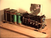
I built a 100W JLH class-A 30 years ago, but it is not bridged.
It is big, and oh-boy does it and the room get hot after a few hours, much hotter than a 100W tube amplifier !
It became a test bed for literally dozens of JLH derivatives.
This is a recent photo, still with some test variations attached.
It is 24 inches (60cms) long. Shown here on its side, with one side removed. The transformer is about 6x6x5 inches. There is a thermal overcurrent cut out on the rear panel; it would pop if you permanently shorted the output wires for more than a few seconds at full output. (Can't even find them these days.)
You can spark its speaker wires noisily together at full input and nothing blows, not even the trip, but that is because it has pure class-A output.
Also, put it beside a 100W class-AB amplifier and it is like having a choirboy beside a rock star; it does not have the dynamics !!!
Pure class-A output current is naturally limited, and it cannot maintain drive through back-EMF induced loudspeaker impedance dips !!!
I had the parts for two, but was so disappointed that the second was never built.
I regard the GEM amplifier as retaining excellent JLH sound quality at normal listening levels, but it is also fully mature and ready to rock, as I am sure Carlos will confirm.
I also expect this circuit to simulate reasonably well on computers other than mine.
My finished monoblocks will use 2SC5200 where 2SC3281 are indicated.
Cheers ........ Graham.
_________________________________________
Bias adjustment.
I initially said link out the class-AB bias pot and set up the 400mA class-A quiescent. Then remove link and add 100mA class-AB bias.
Next I suggested it would be okay to set the AB bias preset at 50% before switch-on, then set 400mA class-AB bias, then the 100mA class-AB. No link would be needed using this method.
Either method is suitable.
__________________________________________
For the first power-up I start with 22 ohm seies power rail resistors and no load. Don't set the bias but check check for unusual heat and the output terminal being at zero, probably within a few millivolts.
Next I remove 22 ohm and insert the 0.22 ohm rail resistors and set the bias with no load by measuring the voltage dropped by one of these resistors. 88mV for setting up the class-A, and then 110mV when the class-AB bias is added.. If everything is okay then test for a few hours and expect the current to increase.
Then back off both biases, remove the 0.22s, and rebias without load whilst still at normal running temperature by using a meter in place of one of the fuses.
For a stable zero at the output keep the input pair away from heatsink radiated heat. If one gets more radiation than the other, you could see drift up to about 25mV.
___________________________________________
Carlos. If the base-emitter junction of the bias control transistor is short circuited before switch-on, then it will be unable to conduct, maximum class-AB conduction will be set up and then the transformer will hum before the fuses flash. If the 0.22 ohm series psu resistors I mentioned are in place you should get away with it (that's my experience anyway) but if not, you would be much more likely to be unlucky.
I once accidentally knocked resistor wires together; this shorted the upper driver base directly to the +ve rail before switch on. Those 0.22 ohm resistors saved the day because only the fuse blew, not even the 2SC3421 !
See, I am not immune to these kinds of mistakes either, but I have had no losses with this circuit, and with the 4 small transistors on a pcb and all others hard wired together on the heatsink with the pre-sets I cannot provoke oscillation by touching anything other than both the input and output connectors simultaneously. As with any amplifier this could cause damage, but it should never arise in real life.
Hi Greg,
As far as I am concerned every amplifier should be running at no more than the original 600 ohms studio standard. Higher audio frequencies are cleaner when pre-amps have a low impedance output, and 600 ohms amplifier input helps keeps the feedback limb impedance equally low.
Lower feedback loop impedance is less influenced by circuit fields, but needs a high quality electrolytic and possibly smaller parallel C(s). (Exactly what you asked.)
It depends on the component used and can easily be checked out by parallelling up during listening tests. It is easier to fit and be sure though.
My PSU is no more than big transformer, big bridge and 2x 10mF per rail before each fuse.
I have more 'C's in the parts box ready for final construction.
Hi EUVL,
I built a 100W JLH class-A 30 years ago, but it is not bridged.
It is big, and oh-boy does it and the room get hot after a few hours, much hotter than a 100W tube amplifier !
It became a test bed for literally dozens of JLH derivatives.
This is a recent photo, still with some test variations attached.
It is 24 inches (60cms) long. Shown here on its side, with one side removed. The transformer is about 6x6x5 inches. There is a thermal overcurrent cut out on the rear panel; it would pop if you permanently shorted the output wires for more than a few seconds at full output. (Can't even find them these days.)
You can spark its speaker wires noisily together at full input and nothing blows, not even the trip, but that is because it has pure class-A output.
Also, put it beside a 100W class-AB amplifier and it is like having a choirboy beside a rock star; it does not have the dynamics !!!
Pure class-A output current is naturally limited, and it cannot maintain drive through back-EMF induced loudspeaker impedance dips !!!
I had the parts for two, but was so disappointed that the second was never built.
I regard the GEM amplifier as retaining excellent JLH sound quality at normal listening levels, but it is also fully mature and ready to rock, as I am sure Carlos will confirm.
I also expect this circuit to simulate reasonably well on computers other than mine.
My finished monoblocks will use 2SC5200 where 2SC3281 are indicated.
Cheers ........ Graham.
Attachments
So Greg, erase from your mind my method, and jump to Graham, he nows more than I.
Of course he nows...he is the father of that children
Related JLH comparison i agree with Graham,
It seems to be two amplifiers with some logical switch on it...a genuine JLH beeing the first amplifier, and when power is increased, it turns a very good AB amplifier... will reproduce more bass and a very clear audio in a full range basis, because of beeing direct coupled reproduce 1 hertz without any problem, and bring with it the advantages of more dinamics and same clarity in trebles range than JLH basic first 1969 design...the one to substitute Williamson tube amplifier.
The ones that apreciate JLH, without any doubt, will apreciate this one too.
Observe that this amplifier is not for sale, so, this is not a Propaganda, this is just our fun to show you something good.
No profit around this subject, in my case, nor an increase of pride, as i did not designed nothing, just cooperate with Graham, that feel always good when people construct his amplifiers and talk real things, making clear and true critics.
My happyness is hear another good amplifier, and to share this with you all.
Yes, maybe some payment, to see Graham happy, and related him also, the happyness is to share with you, i am sure about that.
There's not GM or GEM factory or industry, and there's none intention to be created, maybe, plantpots of things alike, in the future, and as a result of family interests, but no electronic industry or design sales related Graham, the search is for quality and enjoyment.
The ones that construct, please, tell him...he will be happy...me too
regards,
Carlos

Do not remember me the "blameless"
I will start to hit my head into the wall.
The one turned me really nervous...all my printer ink gone to save all those pages.
I was expecting something very good.
What a surprise i had... i am start shaking, and sudoring, sweating, transpiring...the skin is turning redish, arterial pressure is jumping tgo 25 to 21.....
If i died, you are forgived..you do not know how i love to hear this name.
regards,
till the ethernity
Carlos
Attachments

Hi Sam,
Trimodal !
ARGHH NO NO NOOOOOO.
( Carlos - a Trimodal is a Blameless with switchable biasing. )
I really don't want to say any more about it here.
The fact that Douglas Self himself said you can hardly tell the difference in amplification between class-AB and A, says more than he realised.
Cheers ....... Graham.
Graham Maynard said:Hi Sam,
Trimodal !
ARGHH NO NO NOOOOOO.
( Carlos - a Trimodal is a Blameless with switchable biasing. )
I really don't want to say any more about it here.
The fact that Douglas Self himself said you can hardly tell the difference in amplification between class-AB and A, says more than he realised.
Cheers ....... Graham.
There is much that is not blameless about Self's 'blameless' designs....
But being able to tell Class-A from Class-AB is not one of them....
On a level playing field no one can tell the difference....
Hi Sam,
Trimodal !
ARGHH NO NO NOOOOOO. . . . .
Grahm,
I was pretty sure of your reaction in advance. It's Friday and I'm having fun. Couldn't help myself.

My dear old friend Mikeks...i do not know if you understand more about Gluteos ...
The big Poet of our times...Gluteos maximus firmus intrepidus
Or if you understand about Blameless more than máximus.
Well, my wife is old and terrible, in your sittuation i will send Blames to have a meeting with Gluteus maximus and will have fun with that wonderfull picture you post in your avatar.
Hey man...tell me some about her...i am not dangerous (considering our distance) will not compete with you (because distant) and a learn never try to be close to other guy's wives,in special when they are around...ahahahaha
Kidding, naturally, of course
regards,
Carlos
Attachments


ESL adjustments?
Wondering if there would need to be any adjustments necessary for the GEM to run electrostatic panels? Also curious to know if anybody has started layout work for boards? I have a set of JLH boards built and tested but am thinking that the case, heatsinks and power supply ought to be updated and saved for a GEM instead.
Carlos have you settled on a layout yet? Thanks for posting all about this amp. Thank you also to Graham. Regards Moray James.
Moray, already done my way, but not sure if you will consider that a board schematic.
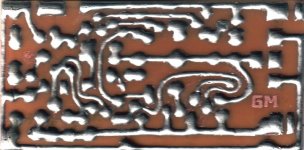
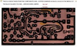
I usually assemble over copper lines, but you can understand the view i attached, as something made over a transparent board, there's the copper lines, and you can make the usual holes and assemble over there as more normal assemble method.
Also i posted a image of the parts over the board to turn easy the construction...by the way, i can understand, in advance of your comments, that someone that use to assemble over traditional computer designed boards can feel unconfortable with my boards, and may loose more time trying to understand "another point of view" than construct your own board.
So, if you want to contribute, usind CAD and create a board for us, will be very well received with many thanks.
Master... from Australia...very good mood, thank you by the support about my opinion.
regards
Carlos
Attachments
- Status
- This old topic is closed. If you want to reopen this topic, contact a moderator using the "Report Post" button.
- Home
- Amplifiers
- Solid State
- Incredible quality amplifier by Graham, prepare your ears for it