There are many modifications you can make
Here you can see some of them.
The ancient Aksas....used bootstrapped circuits too, and they have some identities...but Hugh discovered some modifications that made the amplifier unbeatable...and those are the secrets on Aksa.
Now, lifeforce is very different, but have their secrets too, and could produce a better sound, better bass, deeper bass, fast response, more clear voices and undistorted trebles....beeing better than old 55s
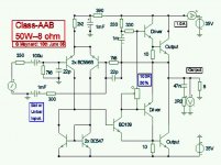
This Graham design works in class A, and produce that class A sonics you already know.
I am suggesting places were you can tweak.
regards,
Carlos
Here you can see some of them.
The ancient Aksas....used bootstrapped circuits too, and they have some identities...but Hugh discovered some modifications that made the amplifier unbeatable...and those are the secrets on Aksa.
Now, lifeforce is very different, but have their secrets too, and could produce a better sound, better bass, deeper bass, fast response, more clear voices and undistorted trebles....beeing better than old 55s
This Graham design works in class A, and produce that class A sonics you already know.
I am suggesting places were you can tweak.
regards,
Carlos
Attachments
This is the old schematic, produce by Graham Maynard
This one was used to produce the suggestion of lay out
No!... this layout was produce using paint.... is simple an not precise, of course, prefer to use something made with eagle or something alike.
regards,
Carlos
This one was used to produce the suggestion of lay out
No!... this layout was produce using paint.... is simple an not precise, of course, prefer to use something made with eagle or something alike.
regards,
Carlos
Attachments
There are two connections missed..for a while
Positive rails filter capacitors...left side filter....the ground side is not connected to the ground line that surrounds the board following counter clockwise direction.
Up rail driver colector is not connected to positive rail.
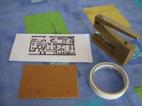
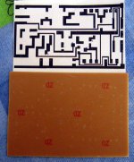
I will show, to the beginers only, how to produce simple boards, hand made.
First:
Prepare the board layout to be fixed over the board.
Carlos
Positive rails filter capacitors...left side filter....the ground side is not connected to the ground line that surrounds the board following counter clockwise direction.
Up rail driver colector is not connected to positive rail.
I will show, to the beginers only, how to produce simple boards, hand made.
First:
Prepare the board layout to be fixed over the board.
Carlos
Attachments
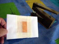
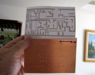
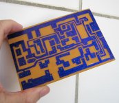
Fix your layout over the board...copper downwards.
The layout is positioned imagining that the board is transparent..and observing by higher position you are watching the components and the copper lines shown because you imaginate the board as transparent.
I hope not too much confused.
hehe
Carlos
The layout is positioned imagining that the board is transparent..and observing by higher position you are watching the components and the copper lines shown because you imaginate the board as transparent.
I hope not too much confused.
hehe
Carlos
Attachments
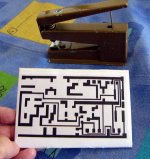
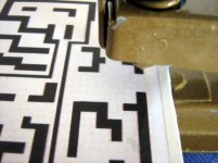
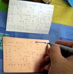
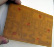
Now turn your layout and turn also your board.
You will have the layout oposite side...seen using transparency...and the copper board with holes.
This is the reference used to trace, by hand, the copper lines.
You may use those permanent ink pens...those famous US pens used to write on glasses...or the one used for transparencies..or some pen you can find to be used to copper board, special to electronics.
regards,
Carlos
Attachments
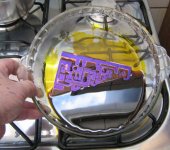
Now let's corrode the copper...the non painted, exposed copper will be corroded
The "acid" used will corrode faster if you make it hot...around 60 degrées centigrades.
Here, i use Iron "Percloreto"...maybe chloride for you...or something alike.
When heated.... go twisting softly to create some "turbulence" that will produce better and faster results.
The copper goes up.
regards,
Carlos
Attachments
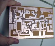
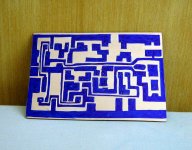
Here is the board...ready to be assembled.
Just following the sketch.
I will not assemble this month...maybe the other.... i have an enormous strip of amplifier under work.... a big line, now counting with 7 amplifiers.
My time is small those last monthes....amplifiers are beeing made very very slowly...alike a turtle...one each 15 days.
When normally i use to spend some hours to complete and listen
Of course..fast work is also a pig work...things turn ugly.
I hope i could help.
regards,
Carlos
Attachments
- Status
- This old topic is closed. If you want to reopen this topic, contact a moderator using the "Report Post" button.
- Home
- Amplifiers
- Solid State
- Incredible quality amplifier by Graham, prepare your ears for it