Looks sweet. But im thinking some thermal resistors could come in handy on the emitter of bd139/140.. then youre very close to a standard amp. Just change the input stage before the VAS to a differential input. And maybe there would be good to have a dominant capacitor to erase oscillation. Also a capacitor series with resistor on the output ?
Hi
this baby seems to have unity gain, create a V divider with a resistor from output to emitter of Q1.
You can also give some smallish (like 0R33) emitter resistors for output transistors and create a 'diamond' at input (add a npn emitter follower) to minimize offset voltage.
Just a first glance, might be wrong.
best regards
oops, i forgot the other resistor that determines the gain...
i would like to stay away from the differential input to preserve a smallish component count (i hope to make this thing portable and stereo)
unless of course, that would help minimize voltage offset. i'd rather not add another transistor between the input transistor and the output driver, because the collector current on the input transistor should be around 120uA to drive the base of the driver transistor, and that's pretty low as it is.
would it be ok to make R4 1k8 and C2 10uf? that gives a roll off frequency of ~8.84 hz, but will it allow enough current through?
Attachments
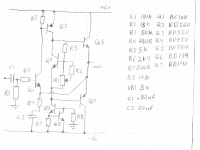
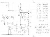
The output DC voltage will be around -0.6VDC, which will not do the Grados any good. Either add a second input device to give near-zero offset, or re-cast the whole thing with +12V supply and capacitor coupling input and output.
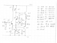
There is no shorted-load protection. Headphone cables get pinched, Q2 and Q6 try to pass infinite current. Your second iteration has 0.33 ohm resistors, cutting shorted-load current to only 18 Amps, a little more than Q6 is rated for and far more heat than you can handle.
I'm glad to see R10 R11 added (how would you adjust bias without a resistor somewhere to stick your voltmeter?) but still think they are too low. 10% of load impedance is a better goal. A more subtle goal (for Class AB operation) is 30mV-100mV at idle current. Assuming AB idle bias is 1/10th of peak current, both "rules" lead to about 3 ohms, not 0.3 ohms.
Trick current mirrors effectively double open loop gain. You may not need such a high feedback factor. Consider dropping Q3, Q4 and Q5, inserting a simple resistor of 1K5 for the collector load on Q1, and increasing R3 from 2K2 to 5K6, giving just under 1mA for the stage current.
Then tie collector of Q2 directly to the positive rail.
This is a much simpler circuit, without the elegant gimcrackery of Q3-5 certainly, but if you study all the classic great circuits - Hiraga, Pass, Bailey, etc - you will find most eschew current mirrors on diff input stages. There is a reason for this, and although the theory would indicate a current source/mirror topology is superior, the listening reveals something different.
Being a phono amp, the rails are tiny at +/-6V. At these voltages and power levels you could gainfully use single ended Class A power; this would very likely sound better. And the feedback cap, at just 10uF, is very low and would result in poor bass performance; best to increase it to 220uF. I presume you are following this with RIAA equalization?
Hope this is helpful,
Hugh
this better?
(thanks so much)
edit-- didn't see AKSA's post, i'll try that. much better for a portable circuit, thanks")
oh, and it's for adapting either my minidisc player or my computer's sound card to my 32ohm headphones. i have no plans for including equalisation circuits at the moment
(thanks so much)
edit-- didn't see AKSA's post, i'll try that. much better for a portable circuit, thanks
oh, and it's for adapting either my minidisc player or my computer's sound card to my 32ohm headphones. i have no plans for including equalisation circuits at the moment
Attachments
you might want to download the free Lt SwitcherCad III Spice
http://www.linear.com/company/software.jsp
drawing schematics is easy and you can simulate to learn about circuit operation
1st pass at varying topologies could use supplied Q models, later you can add manufacturer's models of the Qs you want to use
http://www.linear.com/company/software.jsp
drawing schematics is easy and you can simulate to learn about circuit operation
1st pass at varying topologies could use supplied Q models, later you can add manufacturer's models of the Qs you want to use
ok, here's an update. how does it look to you all?
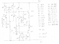
AKSA: i upped the value of C2 to 150uf, it's the largest value i have a convenient source for (unless a polar cap would do better here), i will obtain a beefier value if the bass response is lacking (thanks for the tip). i also got rid of the current mirror, replacing it with a fet based current sink. this makes it exceptionally easy to test if i like the sound better with the fet in or without it
darkfenriz: i made the tail like you describe, thank you for the pointer
jcx: i run gentoo-amd64. spice is in the package list, but it has not yet been ported to my platform. i might just do an x86 install one of these days so i can use more of the neat software that keeps coming up
Attachments
Hi Name773!
A few comments:
-R2 and R12 need to be equal.
-let's place a 10ohm-100nF serial-RC on the output
-Q5 need to be mounted on the heatsink of the output devices. so let's use BD135 here, it's easier to mount.
-in a such simple and little amp I would use bootstrap circut instead of the CCS os the VAS, and a lonely resistor instead of the CCS of the LTP. It's only an idea, the amp with two CCS is very good, of course...
-let's place a iller cap on the base and collector of the VAS transistor (Q4). between 47-100pF will be fine.
-let's place 100nF and 100uF on the rails (if the amp's supply will be two accumulator, they not needed)
-let's place a 100nF cap to the VBE (between collector and emmiter of Q5). It will increase the stability.
-and final: why don't you use a little and cheap IC, for example tda2030, or any other?
Anyway, it's a nice design!
Regards,
Andrew ("edl")
(oh, my bad english... sorry...)
 (i'll do a 32bit install one of these days...)
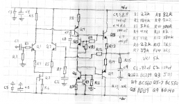
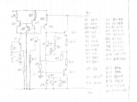
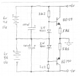
here's my guess at a power supply design, see what you all think
it's heavily based off Sijosae's circuit featured about 3/5 the way down on this page
for this to work more effectively, i would reduce the power coupling caps on the amp boards (C4 & C6) to 10uf each (and polar ones, i forgot to put in the little + symbol).
is this a reasonable circuit? any guesses as to the power draw at idle? it will power both amp channels, hence the coupling caps on each amp board.
Attachments
- Status
- This old topic is closed. If you want to reopen this topic, contact a moderator using the "Report Post" button.
- Home
- Amplifiers
- Solid State
- amplifier attempt #1