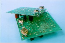
Now I designed Balanced Power Amplifier which use power tr MJ15024/25 for 75WRMS/CH with power supply rals +/- 51V
I had use 2N5415/3440 but now they're out of production. My friend suggest me you can use motolora MJE15030/31 instead of them but I like soud and spec of 2SD669/2SB649
So how can I use both of them or some people suggest me another number of driver
Regard
AHT
I had use 2N5415/3440 but now they're out of production. My friend suggest me you can use motolora MJE15030/31 instead of them but I like soud and spec of 2SD669/2SB649
So how can I use both of them or some people suggest me another number of driver
Regard
AHT
Attachments
aht said:
I had use 2N5415/3440 but now they're out of production. My friend suggest me you can use motolora MJE15030/31 instead of them but I like soud and spec of 2SD669/2SB649
Hi Aht,
It seems that the pair 2SD669/2SB649 is out of production too. It has very good specs, I agree with you. I was constructing an Amp that was supposed to use them. Instead, I've used the pair KSA1220/KSC2690 from Fairchild which is easy to find and has very close specs. The amp is sounding very good.
Besides that, I agree with richieboy, On/Motorola offers a variety of driver transistors which you could use.
Best regards,
João Pedro
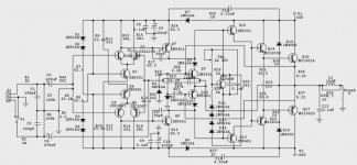
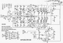
This's my schematic.
I used 15030/31 already but they're required more current than 2N5415/2N3440.
Both sound of RCA & XLR are nearest and close to Audio Analogue Puccini Se Remote in lowcost")
I think it's can be modify to integated amplifier by use passive volume control.
Now it's need some modify to ZERO NFB for possible.
I study from Japan's website they're have sevaral method to modify normal amplifier (NFB amplifier) to the zero NFB amplifier.
If anybody want some pcb design (protel & pdf) can be mail to me for make a little project 75WRMS BALANCED AMPLIFIER.
I hope you'll like this project
Regard
AHT
I used 15030/31 already but they're required more current than 2N5415/2N3440.
Both sound of RCA & XLR are nearest and close to Audio Analogue Puccini Se Remote in lowcost
I think it's can be modify to integated amplifier by use passive volume control.
Now it's need some modify to ZERO NFB for possible.
I study from Japan's website they're have sevaral method to modify normal amplifier (NFB amplifier) to the zero NFB amplifier.
If anybody want some pcb design (protel & pdf) can be mail to me for make a little project 75WRMS BALANCED AMPLIFIER.
I hope you'll like this project
Regard
AHT
Attachments
Hi AHT,
You have strange perspectives.
There are indeed many ways to degrade audio performance. Using low grade or inherently flawed parts is one, removing NFB is another! If you want to go down this path and listen to the raw distortion of OL amplifiers, fine. But to suggest others may want to follow the path is questionable?
I recall coming to your country to correct such misconceptions and the result - they won a "golden ear" . Is there something in the Phrao Chaya drinking water?
Cheers,
Greg
Why not ?
There're many ways to use zero nfb for improve performance of amplifier.
My project still use nfb but I want to modify or change some stage for testing with my (or somebody which downloaded file) experience.
amplifierguru , I like your concept and heard your suggestion amplifier (golden ear) but I want to make something different. Do you have any idea for non nfb ?
Sometime I think non nfb is misconcept but I want to make case study for my life
I have some link and some pictures from Japan website.
http://homepage3.nifty.com/ebina2540/bibou/NO-NFB_Main/NO-NFB_main_mini.html#i
Regard
AHT
Attachments
Hi AHT,
I love that buddhist psyche - it shows in your responses. You are so accepting - even of flawed concepts and at the same time too lacking in 'confidence' to offer something new (another current eclectic thread).
I think the indoctrination of a flawed concept that NFB is bad so should be dispensed with is everpresent in your country. You accept such flawed concepts too easily. NFB is a rock.
Cheers,
Greg
amplifierguru said:
NFB is a rock.
Greg
No Greg, its SOLIDSTATE METAL ROCK
Kanwar
Sorry AHT,
I don't mean to demean - indeed it is the very enterprises such as yours and others in your country that are instrumental in defining a 'home grown' industry which can deflect the hype of overpriced, overhyped and OS audio media favoured (cabals) foreign goods your countries simply do not need.
Go for it. Your citizens should be employed to produce your country's needs.
Cheers,
Greg
How does it work (NON NFB module)
Simulated from circuitmaker had problem ???
After I apply NON NFB module (or DC servo module ?) from Japn website into my schematic by cut feedback resister (52.2K) and make a point A, B between output & feedback point follwing example result is my schematic doesn't work.
It's work as same as not conect feedback loop (output very clipping) so how do I modify this module or design a new schematic ?
Need some help from every guru
Regard AHT
Attachments
2sb649/d669
Hi,
I have just recently taken delivery of 20 pair of 2sb649a / 2sd669a from www.Dalbani.co.uk (nikko electronics) for £10 (about 14euro = $18).
I can recommend them for very good service and an immense range of discretes.
Hi,
I have just recently taken delivery of 20 pair of 2sb649a / 2sd669a from www.Dalbani.co.uk (nikko electronics) for £10 (about 14euro = $18).
I can recommend them for very good service and an immense range of discretes.
Hi AHT,
You have taken a high OL gain amplifier design, disabled the NFB which reduces the gain to a manageable level, and installed a servo for DC feedback to stabilise the DC conditions. But the gain is now very very high open loop - as this is the way the amplifier was designed.
To bring back the gain to comfortable levels you will need emitter resistors of 100 ohms up in the input diff'l stage(s) and some collector R's to ground for the Vas, the problem here is that they will load it too much.
It's impractical with the current cct.
Cheers,
Greg
amplifierguru said:NFB is a rock.
Huh, that's funny. I always thought negative feedback was a crutch.
Charles Hansen said:
Huh, that's funny. I always thought negative feedback was a crutch.
One has to be very careful here.
Do a search on the forum and you will find lots of people for - and against NFB.
I believe NFB bad fame comes from a time (the 80's?) when Japanese makers started the ultra-low distortion spec race.
To achieve these meaningless numbers, they went to massive ammounts of feedback, sacrifiyng all other amp parameters for the nice numbers.
Result? lousy sounding amps, but not due to feedback per se, but due to bad designed (but nice numbers) gear.
NFB, used as should, is a very powerful tool for the (honest) designer.
But then again there are the ones that doesn't like it - same as the never ending argument between solid state and tubes.
Nicely put Jorge.
One only has to look at the vagaries around crossover displayed by Andy c and Mr Evil
http://www.diyaudio.com/forums/showthread.php?postid=673295#post673295
to wonder why anyone would want to listen without NFB removing such. It eludes me.
Cheers,
Greg
One only has to look at the vagaries around crossover displayed by Andy c and Mr Evil
http://www.diyaudio.com/forums/showthread.php?postid=673295#post673295
to wonder why anyone would want to listen without NFB removing such. It eludes me.
Cheers,
Greg
Thanks for suggestion
After my bad idea in non nfb is doesn't work.
I'll find some current feedback amplifier which use transistors as same as my circuit.
May be Jeff Rowland Model9 PCB is coming soon (If a schematic from hongkong is right)
But I still like my schematic
AHT
After my bad idea in non nfb is doesn't work.
I'll find some current feedback amplifier which use transistors as same as my circuit.
May be Jeff Rowland Model9 PCB is coming soon
(If a schematic from hongkong is right)But I still like my schematic
AHT
Attachments
amplifierguru said:One only has to look at the vagaries around crossover displayed by Andy c and Mr Evil to wonder why anyone would want to listen without NFB removing such. It eludes me.
One has to wonder why anyone would use a crutch such as negative feedback to fix such a poor circuit design. It eludes me.
Re: Thanks for suggestion
I think it come from China mainland:
http://www.diyaudio.com/forums/showthread.php?s=&threadid=50083&highlight=
aht said:
May be Jeff Rowland Model9 PCB is coming soon
But I still like my schematic
AHT
I think it come from China mainland:
http://www.diyaudio.com/forums/showthread.php?s=&threadid=50083&highlight=
- Status
- This old topic is closed. If you want to reopen this topic, contact a moderator using the "Report Post" button.
- Home
- Amplifiers
- Solid State
- Best driver for MJ15024/25 motorola transistor