Hi All
I've recently bought a 2nd hand inca tech claymore (great amp..) - it's had its volume pot replaced at some point which now appears to be losing the plot a bit - one channel drops out every now and again, to be fixed by waggling the pot from side to side. I've read on a couple of forums that Colin is sometimes willing to service these old beasts if you can track him down in the wilds of scotland.....which I'm having very little success doing....
Anyone have any idea of contact details for the young fellow?
Thanks in advance
James
Thanks for that - I'd actually found your schematic already on diyaudio! Oddly the pot in my claymore was a 20k, I've swapped it for a 10k and the control is terrible, so I'm going to order a 50k and install that.
I notice on your schematic some of the resistors are 27k, I've gone through my amp noting down the values of all the preamp resistors (as I intend to swap them out for better quality ones), but didnt find any 27k ones ( i think mine are all 47k) - have you any photos of the inside of the amp so I can see where the 27kRs are on yours?
Thanks
James
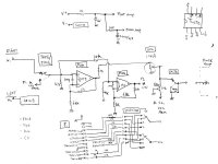
Hi Spev, here is all my works. Pls feel free to discuss for further. Have a nice day.
(ps. I have attached a volume control information for you. Pls check if you have solder the pins correctly. The "IN" is output from former satge and the "Out" pin is to the Line amp. The Line amp is then connected to the Power-amp stage directly. Also I found there is (+) sign marking error at the Claymore PCB of the Power filter cap. I found this error when I desoldered and replaced the oriiginal DC filter caps with some much bigger ones.)
http://i20.photobucket.com/albums/b206/etsang3/MCPhono.jpg
http://i20.photobucket.com/albums/b206/etsang3/Line_ampSelector.jpg
http://i20.photobucket.com/albums/b206/etsang3/SupplyPower_AMP_2.jpg
http://i20.photobucket.com/albums/b206/etsang3/Pow-ampModification.jpg
http://i20.photobucket.com/albums/b206/etsang3/50ARectifier.jpg
http://i20.photobucket.com/albums/b206/etsang3/BigFilterGroup.jpg
http://i20.photobucket.com/albums/b206/etsang3/ChangeZenerSupply.jpg
http://i20.photobucket.com/albums/b206/etsang3/Phono_1.jpg
http://i20.photobucket.com/albums/b206/etsang3/FlatAmp.jpg
http://i20.photobucket.com/albums/b206/etsang3/ThermalTreatment.jpg
http://i20.photobucket.com/albums/b206/etsang3/Spk_term_1.jpg
http://i20.photobucket.com/albums/b206/etsang3/WrongCAPmark.jpg
http://i20.photobucket.com/albums/b206/etsang3/ALPSBlue.jpg
Thanks for all those jpgs, that's fantastic
regarding the incorrectly marked caps - when replacing the cap should it follow the marking on the pcb, or should it be the same orientation as the existing cap? I'm assuming as the cap hasnt exploded that its the pcb marking that's wrong?
I'll play around with the cables running to the alps and see if I can sort out my problems.
Looks like you've made some quite considerable modifications - how does it all sound?
Have you replaced any of the resistors?
Regards
James
I don't know if Claymore got more PCB version. I suggest you flip over the current working PCB and test the 2 points of the cap and note down the polarity. It is the most secure way. Don't follow the PCB, I found a version with mistake so should take great care.
The amp is not owned by me so I've just tested a while and returned to my friend. I have actually mod. it to a DC amplifier which the Freq. Resp. can start from 0Hz now. It is amazing that the DC shift is so stable, it may due to I made a lot of thermal coupling to align the temperature of critical components. Also, Since the amp use MOSFET output device with higher input capacitance. I tuned the idle current to ~200mA (!!! only good thermal transfer is made) and the amp is quite warm now.
Compare before it was modified, the character of the amp did not changed. In addition, the bass is much lower and cleaner. I can hear more type of bass after the mod. This is facilitate by those large filter to reserve energy to be use and extend the amp freq. resp. to 0Hz.
Also, the extension of high end freq. (higher idle current) bring a clearer sound stage (air image) of the background. I tested with a Sound Track CD "Brave Heart" and
I felt like sitting at a big cinema.
Have you replaced any of the resistors?
For High level amplification (i.e. power-amp), I don't think better resistor will bring audible enhancement. The signal is much higher than the noise of the resistor. If the resistor is more stable vs. temperature, it is worth to use for power-amp. I think change to basic 1% metal film resistor (low price) will be enough.
I want to point out that Claymore PCB is poor quality which can be damaged easily. It is also not real Plate-Thru-hole PCB required soldering of both side. If you slightly damage a hole (the copper pad is bend off the PCB surface) with upper and lower track, you may need to use a rivet to fix the hole. (better to sue a 30W iron except soldering those big DC filter cap. Good Luck.
if you haven't already done so, I can recommend changing the TL072 opamps in the preamp stage - I've currently got AD8620s in my claymore which have added much more detail and clarity to the sound - it may possibly enhance your friend's amp even more.
Yes the pcb is pretty poor - I've already managed to lift and tear one of the pcb tracks running to the vol pot - so it's now hardwired...
considering removing the balance pot, mute and tape monitor switches now and just running wire across...
Yes the pcb is pretty poor - I've already managed to lift and tear one of the pcb tracks running to the vol pot - so it's now hardwired...
considering removing the balance pot, mute and tape monitor switches now and just running wire across...
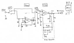
Hi Spev, friend of here told me that I have a wrong drawing. Thank you.
Here is the corrected drawing. Resistor R17a should be 10k.
Wrong drawing to Load Resistors of Tr1a and Tr2a.
http://i20.photobucket.com/albums/b206/etsang3/Pow-ampModification3.jpg
I will ask my friend if he want to try new opamps. I got AD797 , AD827, OPA627, OPA2604 etc...
Good listening.
(Do you know Nait-2 ? what is your comment ? I am going to do mod. on it with my friend. We will post the works here later.)
Hi James, from the photo, you can see a copper plate soldered to all caps to make a ground as well as holding them. There are 2 ~3mm copper pins soldered from the plate to the GND track of the PCB solder-side. The pins are good enough to hold the caps at the right place. The caps were not held 100% firmly cause I did not glue them.
Pls feel free to ask more questions as you like. You are welcomed.
Marry Xmas.
Pls feel free to ask more questions as you like. You are welcomed.
Marry Xmas.
I'm considerng using 4 of these:
http://uk.farnell.com/jsp/endecaSearch/partDetail.jsp?SKU=652179&N=401
are they the cap you used? Did you consider using any other caps, such as bhc aerovox, kendeil, vishay bc?
I obviously want to install the best caps possible....
thanks
http://uk.farnell.com/jsp/endecaSearch/partDetail.jsp?SKU=652179&N=401
are they the cap you used? Did you consider using any other caps, such as bhc aerovox, kendeil, vishay bc?
I obviously want to install the best caps possible....
thanks
http://uk.farnell.com/jsp/endecaSea...KU=652179&N=401 , yes , I was using those. It was easier for me to get Japanese stuff in HK and they are good enough. It seems to me that USA and European caps are bigger in size so not suitable. When you increase the cap capacity up to 6 x 10,000uF (+ rail & -rail) like me. The initial charging current to the caps will be high so the rectifiers need be changed. I think using a 10A normal 50-100A surge Fast Recovery or Schottky Rectifier can fit the job. You need to buy 4 of them and replace those 4 on the board. Actually, Calymore consumes only 1-2A at idle (In my case, I use a 50A traditional Bridge Rectifier)
Have a nice day.
Have a nice day.
You can contact me via e-mail
Cj14wonfor@gmail.com
More info from
Home | SECA
Facecrap page
Elsdon Wonfor Audio - Home | Facebook
Cj14wonfor@gmail.com
More info from
Home | SECA
Facecrap page
Elsdon Wonfor Audio - Home | Facebook
Wow! it only took you 12 years .
Must be a major record for attentive service.
No it took two hearts attacks, one coma, two strokes,major back and inner operations, a marriage break up and the theft of the company I started followed by a nervous breakdown.
Oh and becoming homeless.
No real problem as you can read.
And you excuse is?
")
- Status
- This old topic is closed. If you want to reopen this topic, contact a moderator using the "Report Post" button.
- Home
- Amplifiers
- Solid State
- Colin Wonfor Contact Details?