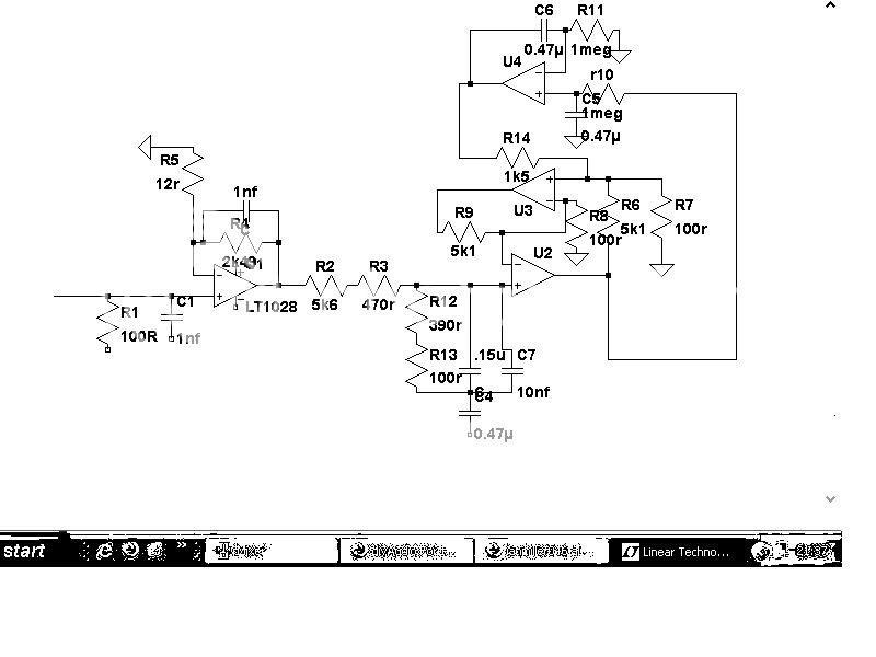
your output offset servo destroys the gain matching condition for the output active compensation - R14 is too small and should be moved, why not 1 meg into U2 +in, 1 Meg hardly effects component tol error at U2 +in
not that I think active compensation is particularly useful in any event, Jung's multiloop composites are likely to be more useful in this location as the phono pre out may drive cable C and variable impedance - which also detracts from the active compensation
your images are so large so you can't tell but jpeg really sucks for denser drawings with small text - use .gif
I've got some info on my web page about one popular active RIAA equalization circuit, including getting the circuit to match the Neumann time constant, computation of RIAA equalization errors using SPICE, as well as separating out the op-amp induced portion of the error. The link can be accessed via the WWW button below this post.
they aren't my designs, but they both work and sound v good. They are both well known circuits of items.
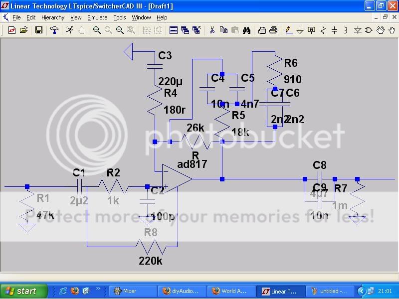
Its my first attempt at uploading, so be patient...any tips gratefully received
Any comments about the top circuit (should I post in the vinyl section?), it uses single supply and is my fave phonostage to date.
Its my first attempt at uploading, so be patient...any tips gratefully received
Any comments about the top circuit (should I post in the vinyl section?), it uses single supply and is my fave phonostage to date.
Hi Andy,
Excellent investigation.
My best sounding phono pre-amp split the RIAA process into two so that one IC was not working over such a wide gain/frequency range.
Following a separate buffer with pre-setable variable R + C cartridge matching, the first active IC created the low frequency lift to 20Hz ( not 50Hz ) plus the gain necessary to acheive the required midband output level.
There was separately switchable 'rumble' filtering for discs where the extended low frequency response shook the room.
All ICs were run flat gained through mid to hf, so no equalisation could go wrong at any stage, just plenty of headroom via the psu rails.
This was followed by precision resistor-capacitor passive filtering for the upper RIAA characteristic, and of course it simultaneously cut high frequency noise and hf distortion products from the first two stages.
Finally there was an IC output plus transistor buffer, which could now cover the Neumann time constant.
It sounded superior, no matter what the dB figures suggested, and where every dB of signal to noise ratio is so important it was fractionally quieter too.
It's low impedance output was totally isolated from the RIAA equalisation IC/circuitry so the sound could not be 'sucked' or dynamically challenged by power amplifier or cable impedances.
I had bought our home and little feet had arrived so I needed money; I sold it for £100 about 25 years ago. £36 of that was for the ICs alone, and this was a fair expense in those days, but I'm blowed if I can remember their make or number now; they were the latest high spec of their day. The guy who bought it kept coming back to tell me how he was amazed by the open-ness, clean-ness of attack, stability of sound and sheer clarity.
Aspects not heard via conventional 'all-in-one' RIAA equalisation stages, no matter how good the base amplifier.
I would love to see your type of investigation cover something like that, maybe including noise performance as well as amplitude/frequency.
Cheers ......... Graham.
As to the newman constant, has it been proven that we can actually hear the difference between two circuits where one is corrected for it and another not?
Some spice programs (later OrCAD versions for example) come with optimizers and one may be able to just use that function to let the computer find optimal values for the equalization network. Not sure if that has been done by anyone.
Some spice programs (later OrCAD versions for example) come with optimizers and one may be able to just use that function to let the computer find optimal values for the equalization network. Not sure if that has been done by anyone.
Yes, that's been done by Jim Hagerman. There's a link to his analysis in my article, but for convenience I've duplicated it here. http://www.hagtech.com/pdf/riaa.pdf
Closed-form solutions are nice because you can just take the formulas and put them into Excel, MathCad or whatever. One of the issues with optimization is that there's not always a way to constrain the optimizer so that it is forced to pick R and C values from a list of standard values. Often the deviation of the calculated value from the standard value can be much more than the tolerance of the component itself.
Closed-form solutions are nice because you can just take the formulas and put them into Excel, MathCad or whatever. One of the issues with optimization is that there's not always a way to constrain the optimizer so that it is forced to pick R and C values from a list of standard values. Often the deviation of the calculated value from the standard value can be much more than the tolerance of the component itself.
Along the lines of what Graham suggests, I have found the best sounding phono stage to use "split passive" EQ. Isolating the two halves of the RIAA. Using non-feedback means of creating the rolloff. Art Loesch got me into this idea.
The current rage is "T" inductor networks, but having not played with them, no opinion is offered.
For solid state I'd give some serious consideration to using a discrete gain stage and higher B+ with class A biased output devices. I am reasonably certain this is what Spectral did in their model 10 & 20 preamps some time back. Doing this I like FET & Mosfet, but you may not think the same way about it.
Even using this method, and given that LP isn't an inherently "accurate" medium in many ways, it's my view that tubes do this job way better from a purely subjective listening perspective. Seems like more music comes out when well implemented.
When using tubes, I still use a FET for low noise in the front end...
as always Ymmv.
_-_-bear
Hi lt,
That's a strange question for me to receive, for I wonder what relevance background has.
Some excellent audio/electronics has come out of 'arty' folk.
The two people who inspired me most.
Sir Douglas Hall, for his circuit imagineering capabilities.
See
http://freespace.virgin.net/spontaflex.reflex/
My high school A-level Physics teacher, who showed me the importance of understanding basic fundamentals.
My most inspiring read
The Romance and Reality of Radio, by Captain Ellison Hawks, 1923
I value genuine interest and dedication more than background; mine is somewhat varied, but 'hands-on', and my iron is still smokin'.
Actually its a wonder I don't have lead poisoning!
Cheers ......... Graham.
Graham Maynard said:Excellent investigation.
[...description of another phono preamp circuit...]
I would love to see your type of investigation cover something like that [in reference to circuit described above], maybe including noise performance as well as amplitude/frequency.
Hi Graham,
Thanks for you kind words. To tell you the truth, I don't even have a phono setup at the moment. My records are mostly worn out ones that I had in high school. I do have a Linn Sondek LP12 that's dead, so I should really fix it or get it fixed.
That writeup on my web site is something I originally dreamed up when I was in grad school twenty-five years ago (sheesh, am I really that old?
") ). The teacher did a Foster's expansion of an RC impedance and it looked just like an RIAA network. So I decided to investigate. I had thought of trying to publish the results until I looked in the AES journal and saw the article by Lipshitz. Needless to say, I decided against that idea.
). The teacher did a Foster's expansion of an RC impedance and it looked just like an RIAA network. So I decided to investigate. I had thought of trying to publish the results until I looked in the AES journal and saw the article by Lipshitz. Needless to say, I decided against that idea.But since I hadn't seen any published reference showing a closed-form solution that included the Neumann time constant, I decided to put it up on the web. It took a lot longer to write up than I thought it would.
Oh well, maybe someone can make use of it.
Hi Andy C,
why was this Neumann thing put there?
Does it give any advantage?
And that 20Hz roll off is balderdash (good english word from a Scotsman).
I support the toplogy of splitting the time constants and putting the 75uS last even without a final buffer, provided you keep the next stage impedance high (say>= 50k).
AndrewT said:why was this Neumann thing put there?
Does it give any advantage?
The background is described in the article a bit. There's a link to Allen Wright's web page where he goes into more detail about it. The idea is that the equalization actually used is not exactly what the RIAA specifies because it's impractical for the high-frequency boost of the recording to continue to too high a frequency. So it seems logical to compensate for the actual equalization used in the most common cutting lathe.
And that 20Hz roll off is balderdash (good english word from a Scotsman).
Yes, I agree there.
I support the toplogy of splitting the time constants and putting the 75uS last even without a final buffer, provided you keep the next stage impedance high (say>= 50k).
Sure. The purpose of the article was to describe how to get a specific configuration to have the most accurate equalization possible, not to advocate any particular configuration. If you're interested in building such a circuit, it may help you. If not, it makes no never-mind to me
I don't see any point in adding the cost/complexity of extra active stages and noise/distortion input stages to something that can be achieved simply with one full RIAA feedback stage with a small added hf loop zero and following passive rolloff.
I have done this in a commercial preamp with a single op amp with the RIAA network declining at hf to about 2K2 ohms and a passive rollof immediately after. this way you have only one op amp noise/distortion source, retain full (maybe 40dB) overload margin, ....
Greg
I have done this in a commercial preamp with a single op amp with the RIAA network declining at hf to about 2K2 ohms and a passive rollof immediately after. this way you have only one op amp noise/distortion source, retain full (maybe 40dB) overload margin, ....
Greg
Hi Andy and Andrew,
I believe I would still do the 20Hz roll-off today, but have it switchable.
Is it wrong to have such an option ? Especially for rock and pop ?
Have you actually heard it, so that you have experienced the sound with real ''Hi-Fi'' loudspeakers ?
Cheers ........ Graham.
I believe I would still do the 20Hz roll-off today, but have it switchable.
Is it wrong to have such an option ? Especially for rock and pop ?
Have you actually heard it, so that you have experienced the sound with real ''Hi-Fi'' loudspeakers ?
Cheers ........ Graham.
amplifierguru said:I don't see any point in adding the cost/complexity of extra active stages and noise/distortion input stages to something that can be achieved simply with one full RIAA feedback stage with a small added hf loop zero and following passive rolloff.
I have done this in a commercial preamp with a single op amp with the RIAA network declining at hf to about 2K2 ohms and a passive rollof immediately after. this way you have only one op amp noise/distortion source, retain full (maybe 40dB) overload margin, ....
Greg
Of course, you have to be happy with your own system.
But there is really no extra noise added that is worth a damn, since the noise floor of your LP is WAY, way higher than the noise floor of any half decently designed and built circuit... especially in solid state.
Since the implementation is so "simple" why don't you *try* a split passive RIAA?? See if you hear any differences? Maybe you won't. Maybe you will. Of course your implementation will make a difference. At least it has appeared so to those who have rather thoroughly investigated many variations on this theme... maybe you will see something in it?
As always ymmv.
_-_-bear
- Status
- This old topic is closed. If you want to reopen this topic, contact a moderator using the "Report Post" button.
- Home
- Amplifiers
- Solid State
- riaa circuit