hi
here s the mosfet amp i m tryin to build : http://users.swing.be/edwinpaij/ampli_mosfet_simple.htm
i have 3 questions ...
1- i m tryin to use irfp250 instead of irfp240 ... is there any problem ... ?
2- can i use 4 output transistors in array instead of 2 transistors (to gain more power) ?
3- can i build two seprated of this amp and brigde their output together (to double the output power) ???
thnx ...
Yes. The amp is not really suited to either. Because there is not much in the way of thermal compensation it may just keep heating up. You may be lucky and get away with it but the design is not inherently safe.
The IRF devices are listed in the parts list alongside a bunch of lateral (audio) devices which are safe. I wonder if the author has really properly tested the design with vertical (switching, e.g. IRF) devices.
The amp will probably only cope with one pair of vertical output devices because vertical devices have much higher input capacitance = harder to drive.
You can bridge any amp as long as you only run double the usual impedance.
1 - from the datesheet, the IRFP250 looks like two IRFP240 chips in a single package. Much higher gate-source capacitance. It does not have a compliment. Stick with the 240.
2 - Adding more transistors won't add more power, per se, but it will enable you to get more power reliably into lower impedances. To raise the power output you need to increase the rail voltage, which often drives you to more output devices for reliability
3 - that design is bridgeable in theory. If your output stage and power supply are up to the task, you can get four times the output power of each amp by itself. Bridging presents an apparent load to each amplifier that is half its actual value. So each half of the amp "sees" a 4 ohm load if you use an 8 ohm speaker. This means more current and higher dissipation.
A problem with the design as it stands is it needs a more robust output stage to reliably operate bridged at high power (or even normally) I would use at least 3 pairs of output devices, if not four or more, depending on your heat sink. Smaller heat sinks require more output devices. Duplicate R12-15 as many times as you have output pairs.
Note that the stereo version on that page has inadequate heat sinking. If not for the fan it would die, and that arrangement wastes a lot of the fan's cooling capability. The monoblock is better for heat sink size, but be sure to permit adequate airflow.
Another issue is thermal stability. You'd be better off with a Vgs multiplier (see http://passdiy.com/pdf/A75p1.pdf for an example and discussion) with the transistor mounted on the main heat sink. With just a pot to set bias you leave yourself open for thermal runaway.
You would probably be better off building one of Rod Elliot's designs http://sound.westhost.com/projects-1.htm. or a Leach amp http://users.ece.gatech.edu/~mleach/lowtim/ . Ready made boards make the projects a lot easier and more likely to be successful. I don't have experience with Rod's amps, but there are plenty of folks here who have built them and love them. I am happy with my Leach amps.
hi & thnx
my goddd !!! i searched all the country for irfp240 & i couldnt find it ... somebody told me that the irfp250 will work for it ! ,, but it seems the irfp250 & irfp9240 is not compliment as u said , so the amp will not work at all ?????!!!
and i have not any problem for heatsink , i wanna use it w a larg heat sink and fan colling system for high duty use , ...
i m tryin to build the leach super amp for another use , and i want this amp as a bridgable amp to use as a guitar amp ... and also another single one to drivin my sub ... any suggestion ?
my goddd !!! i searched all the country for irfp240 & i couldnt find it
... somebody told me that the irfp250 will work for it ! ,, but it seems the irfp250 & irfp9240 is not compliment as u said , so the amp will not work at all ?????!!! and i have not any problem for heatsink , i wanna use it w a larg heat sink and fan colling system for high duty use , ...
i m tryin to build the leach super amp for another use , and i want this amp as a bridgable amp to use as a guitar amp ... and also another single one to drivin my sub ... any suggestion ?
richie00boy said:Yes. The amp is not really suited to either. Because there is not much in the way of thermal compensation it may just keep heating up. You may be lucky and get away with it but the design is not inherently safe.
The IRF devices are listed in the parts list alongside a bunch of lateral (audio) devices which are safe. I wonder if the author has really properly tested the design with vertical (switching, e.g. IRF) devices.
The amp will probably only cope with one pair of vertical output devices because vertical devices have much higher input capacitance = harder to drive.
While I would prefer to see a Vgs multiplier for a bias voltage
source, it is not a given that the bias will be unstable, as long
as adequate sinking is provided, the power supply is fairly
constant, and the bias is adjusted after warm-up. Larger
values of Source resistance will improve the bias stability.
As to the relative capacitance of Lateral vs Vertical, this has
been hashed out in these threads at length - the specified
capacitance of the two types often shows the Lateral as
actually having greater capacitances. It is the linearity of
the capacitance which becomes the issue in any comparison.
IRF250's will probably work as well or better, and I observe that
for every design there is an optimum number of paralleled
devices, and often the number is greater than 1.
Nelson Pass said:It is the linearity of
the capacitance which becomes the issue in any comparison.
Nelson, is it the linearity (straightness of the capacitance curve) or general slope of such a curve that matters?
For example, of two devies, one with a constant capacitance (perfectly linear), and another with a perfectly sloped capacitance (perfectly linear two), which one should we prefer, assuming everything else equal?
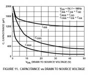
Any character of the device which is not constant over the
operating area gives rise to distortion. The variation in
capacitance with voltage creates distortion at high frequencies
not seen at low frequencies. Of course we would prefer a
constant value, but if we have to accept variation, it's a lot
easier to put up with a gentle variation, which is one reason
we say that Mosfets like voltage: the capacitance and
capacitance variation is less when there is greater voltage
across the device.
which is one reason we say that Mosfets like voltage: the capacitance and capacitance variation is less when there is greater voltage across the device.
Mosfets prefers higher working voltage (Vgs I assume)
Do bipolars works better in higher voltages too? Or in the contrary bipolars prefers low operating voltage (the cascoding in VAS for example)?
Let me ask the question in a slightly different way:
two otherwise identical MOSFETs: one's capacitance goes from 900p to 100p, in a perfectly linear fashion. another's capacitance fluctuates between 400p and 600p randomly (thus, perfectly non-linear).
Which of the two devices would you prefer?
two otherwise identical MOSFETs: one's capacitance goes from 900p to 100p, in a perfectly linear fashion. another's capacitance fluctuates between 400p and 600p randomly (thus, perfectly non-linear).
Which of the two devices would you prefer?
lumanauw said:
. . . (Vgs I assume). . .
I assume this way.
Attachments
tlf9999 said:Let me ask the question in a slightly different way:
two otherwise identical MOSFETs: one's capacitance goes from 900p to 100p, in a perfectly linear fashion. another's capacitance fluctuates between 400p and 600p randomly (thus, perfectly non-linear).
Which of the two devices would you prefer?
Tough call. I would try both out, and see what happens. We
have to be clear in understanding that both create distortion,
and its a choice between magnitude and character. Usually
I prefer character, but it depends on how "perfectly nonlinear"
your example might be. If it's really random, then the harmonics
will have high order, and I really dislike that.
Relevance ?
With a well designed and low impedance output driver stage the effects of gate capacitance can be minimised to a negligible (non-audible) level. A low impedance drive will swamp out any variations in capacitance.
Visually this can be observed with a 10Khz full rail swinging square wave where with a well designed driver stage the effects observed are quite small. (IMO).
Cheers
amplifierguru said:Indeed Quasi,
See my 5ohm drive impedance MOSFET 150W power amp,
with the BC546 30mW driver!
It's a goer.
Greg
Whats you damping factor.....using BC546 as a driver WOW! Great
Yes you can, but .....
Hi Ahmad_tbp,
Yes you can but you must include thermal tracking compensation in the voltage multiplier stage or elswhere that will reduce the bias current as things warm up and things WILL warm up. Let me explain;
In order to achieve an output signal free of crossover (switching)distortion you must bias the output stage so that output devices are always on at low signal levels. This produces heat.
Unfortunately with the IRF fets you are talking about, as they get warm they will conduct more and then get warmer and conduct more and get hot and conduct heaps and then KABOOM!. This tragic result is guaranteed with the circuit you posted if you do not insert themal compensation. Some methods have already been suggested here and elswhere in this forum.
Very large heatsinks may not help that much because the heating is too localised. This is why most amp layouts have the "thermal detector" very close to the FETs.
As far as circuits go you should look at the amp I posted in "power amp under development" and also Lars' ZETA.
The amp I posted has been built and is currently out on loan to an audiophile friend of mine who wanted to give it a run. Repeated phone calls have failed to get the amp back....so I think he likes it.
Good luck & cheers
- Status
- This old topic is closed. If you want to reopen this topic, contact a moderator using the "Report Post" button.
- Home
- Amplifiers
- Solid State
- mosfet amp questions ...