hi quasi ...
and thnx for help ..
but if u remember me ( my subwoofer construction thread ! u helped me so much there ) i have not much experience in electronic ,,, if i want to be honest i really donno what r u talkin bout lol ! .. sorry ...
how can i control the bias current ... ?
u suggest me to build ur amp ,, is ur amp have a pcb layout ? ..
cuz i cant convert the schematic ...
EUVL said:Is it your experience that vertical FETs have in general a more gentle variation in capacitance with frequency than lateral FETs ?
I don't work with Lateral devices very often, but it is my
understanding from Charles Hansen that they have less
non-linearity in the capacitance.
I think that this is an issue when considering their use as
a Common Drain (follower) or as Common Source (having
voltage and current gain) Lateral Mosfets have some
advantage in the former if the driving impedance is high, and
Vertical Mosfets have some advantage as followers
When the impedance driving any of these is low, the problem
tends to go away, and then the issue is more what
transconductance you want - the Verticals being quite a bit
higher. I deal with this issue a lot because I favor 1 and 2
stage designs, and giving the transistors a low impedance
source often means yet another stage, so I have to make
my trade-offs accordingly.
Nelson,
We discussed once about a year ago in a private email communication about 2SK1529, which you suggested could be a lateral FET. I checked the Toshiba website but still could not come to conclusion whether it is one or the other.
According to my measurements (Id vs Vgs using 1 kHz sinewave), the 2SK1529 has, within 10%, the same transconductance as IRFP240 at around 1A (the quoted value is much higher for IRFP240 in the datasheet, but at a much higher current; it drops also proportionally to bias current, so at 1A, it is about the same as the Toshiba), but the 2SK1529 has much lower capacitance. So my conclusion from the measurements was that the 2SK1529 is at least a equal replacement for IRFP240 in e.g. an Aleph-X. Different story for the likes of 2SK1058, that I agree.
Perhaps Charles would care to shed some light on the topic?
Patrick
Ahmad_tbp said:hi quasi ...
and thnx for help ..
but if u remember me ( my subwoofer construction thread ! u helped me so much there ) i have not much experience in electronic ,,, if i want to be honest i really donno what r u talkin bout lol ! .. sorry ...
how can i control the bias current ... ?
u suggest me to build ur amp ,, is ur amp have a pcb layout ? ..
cuz i cant convert the schematic ...
Of course I remember, hows the box going?
Anyway schematic, layout and tracks are on these links;
www.diyaudio.com/forums/attachment.php?postid=600264&stamp=1111145851&
www.diyaudio.com/forums/attachment.php?postid=600267&stamp=1111145980
www.diyaudio.com/forums/attachment.php?postid=601021&stamp=1111237713
If you decide to build this please contact me so that I can provide a construction guidline (heatsinking, wiring layout etc.)
Cheers
> Susan Parker is under the impression that the 2SK1529 is
a lateral part.
She got the FETs from me. : )
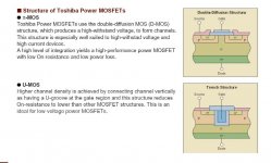
According to a broshure on power FETs from Toshiba, they refer 2SK1529 as pi-MOS. From the picture, it looks more lateral than vertical to me. In any case, it is D-MOs, and has the characteristic "linear" region after the parabolic at low current.
Patrick
.
a lateral part.
She got the FETs from me. : )
According to a broshure on power FETs from Toshiba, they refer 2SK1529 as pi-MOS. From the picture, it looks more lateral than vertical to me. In any case, it is D-MOs, and has the characteristic "linear" region after the parabolic at low current.
Patrick
.
Attachments
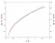
And this are the measured Vgs vs Id curves for both IRFP240 and 2SK1529. As one can see, transconductances is practically identical at around 1A.
Measurement was done at Vds = 24V, with the gate driven by a function generator using 1kHz sine wave with appropriate DC offset. Single shot, 1000 measurement points, 16 bit.
Unfortunately I have no equipment to measure distortion or frequency dependent capacitance. If anyone is able and willing, I am more than happy to offer a couple of FETs, for the sake of knowledge for all.
Patrick
Attachments
As far as the SK1529/1530 SJ200/201 being Verticle or Lateral makes no difference with these devices as far as bias tracking is concerned in audio amps. It is my understanding that these devices are Lateral but the negative Tempco doesn't kick in till 6Amps with the 1529 (higher for the 1530). As far as audio is concerned these should be treated more like Verticles. Some even consider them Verticles. I just consider them Fets that need a Vbe Multiplier for bias stability 
As for using them in the schematic in the first post, they may work and not have thermal runaway with big enough heat sinking as Nelson suggest, or not. You would be taking a chance with bias tracking using only a Pot for bias. Its not that hard to add a Vbe multiplier, and i personally would.
Another thing that needs considertion is the Vgs on value. For the 1058/1529 162/200 this value for a class AB amp is about 1.5 V. For the IRF devices this is typically ~4 V. What I'm getting at is that the IRF devices need a different bias voltage, and could have very bad cross-over distortion used in the circuit without taking this into consideration. (I'm not sure if the author of the amp posted in post #1 has or not, but I get the feeling that the amp was designed with the 1058/162 devices in mind).
-D.
Getting back to post 1 :
The schematics i have seen on Edwin Paij's homepage are not by his hand.
I would have more faith in circuits that were designed and tested by the same person, this one was originally intended for Lateral SJ/SK Mosfets.
And even then it wasnt that great.
The schematics i have seen on Edwin Paij's homepage are not by his hand.
I would have more faith in circuits that were designed and tested by the same person, this one was originally intended for Lateral SJ/SK Mosfets.
And even then it wasnt that great.
Dozuki said:What I'm getting at is that the IRF devices need a different bias voltage, and could have very bad cross-over distortion used in the circuit without taking this into consideration.
That's quite simple to solve: rather than using a Vbe multiplier, use a Vgs multiplier. Just make sure that Vgs characteristics of the multiplier is similar to that of the output devices.
Actually I was refering to the original schematic that just uses a Pot for bias. You would have to make sure that the Pot would drop enough voltage to turn on the IRF devices. If it does not (depends on what the current in that leg is set to) you could increase the size of the pot to get it to drop more voltage. You would have to be fairly selective of the pot value in order to get the bias just where you wanted it. But it still has no thermal tracking.
A Vbe multiplier would do fine in this case. Granted a BiPolar would track the temperature differently than a fet for the multiplier, but in practice this works and is a better solution that just using a Pot. I've always used Vbe multipiers with the SK1529/SJ200 Fets and this works well. It should do just as well with IRF devices.
A Vbe multiplier would do fine in this case. Granted a BiPolar would track the temperature differently than a fet for the multiplier, but in practice this works and is a better solution that just using a Pot. I've always used Vbe multipiers with the SK1529/SJ200 Fets and this works well. It should do just as well with IRF devices.
The IRF's typically start to get up at around 3V, so I can't see why a simple string of 1A diodes in series with the pot and as many in thermal contact as needed for tracking.
Putting numbers to it, given you have a 0-2V pot range you will need it built up by about 5V with about 5- 6 Vbe's included = 6 thermal tracking diodes (for 3.6V) + say 2 non-tracking diodes.
Or even 5 tracking + 1 red LED.
Too easy.
Greg
Putting numbers to it, given you have a 0-2V pot range you will need it built up by about 5V with about 5- 6 Vbe's included = 6 thermal tracking diodes (for 3.6V) + say 2 non-tracking diodes.
Or even 5 tracking + 1 red LED.
Too easy.
Greg
wow what s goin on in here !!! 
wat r u talkin bout ?! lol
thank u so much quasi for the layouts ...
how much watt ur amp can handle ? ...
and can i use irfp250 or other mosfets in that ? ...
i really like to build ur amp ...
..
the box was built but ..... the sound s really bad
i bought two rcf full range 12" speakers and built a 4x12" cab w 2 subs and 2 rcfs w the help of simon , but the subs r realllllyyyyyyyyy s**** in a little high volume , there s no sound comin out from them just some very loud noise like " tagh tagh " somethin like a wiplash sound i can t explain it good in english sorry .... i back to my computer speakers for my bass guitar and tryin to earn some money for a marshall bass amp ! lol ...
wat r u talkin bout ?! lol
thank u so much quasi for the layouts ...
how much watt ur amp can handle ? ...
and can i use irfp250 or other mosfets in that ?
... i really like to build ur amp
... ..
the box was built but ..... the sound s really bad
i bought two rcf full range 12" speakers and built a 4x12" cab w 2 subs and 2 rcfs w the help of simon , but the subs r realllllyyyyyyyyy s**** in a little high volume
, there s no sound comin out from them just some very loud noise like " tagh tagh " somethin like a wiplash sound i can t explain it good in english sorry .... i back to my computer speakers for my bass guitar and tryin to earn some money for a marshall bass amp ! lol ...Hey Ahmad_tbp;
Yes you can use the IRFP250 with no problem at all.
How much power you will get depends on your power supply as well as the capabilty of the amp module.
The board can take a total of 6 FETS and yes you can use IRFP250s. Note this amp does not use P channel FETs.
The module will safely handle + / - 70 volt DC rails. This will give just over 200 watts into 8 ohms and around 360 watts into 4 ohms.
As a rough guide you will need a 500va transformer with at least 20,000 uf of capacitors.
Note the construction of the small heatsink and that T8 mounts under the board into a small hole in the main heatsink. All the main FETS mount under the PCB.
Cheers
Well....
Well yes you can with my design provided that;
1. The FETs Vds is at lease twice your rail voltage i.e. if your rail voltage is + / - 70 volts then your FET must be rated to at least 140 volts (160 for safety)
2. That you use only about 35% of the FETs power rating plus very good heatsinking, i.e if you have 6 FETs rated at 180 watts each then your amp should not be asked to deliver more than 375 watts of RMS power. (this is a very rough approximation without doing complex calculations).
So you can use almost any power FET. Note though that different FETs will have different characteristics such as input capacitance, transconductance and on resistance to name a few.
The amp I built runs +/- 73 volt rails and uses 6 IRFP450. I loaded it with 4 ohms at full RMS sine power for 20 seconds when I tested it. Note that sine wave testing is a very severe test for an amp and is nothing like normal music.
IRFP450s are basically higher voltage IRFP250s so if you build the amp you will find it very reliable. Under music it has been running for more than 2 months often at full power.
Cheers
Ahmad_tbp said:hi quasi again ...
so i can use any N channel FETs yeah ??
Well yes you can with my design provided that;
1. The FETs Vds is at lease twice your rail voltage i.e. if your rail voltage is + / - 70 volts then your FET must be rated to at least 140 volts (160 for safety)
2. That you use only about 35% of the FETs power rating plus very good heatsinking, i.e if you have 6 FETs rated at 180 watts each then your amp should not be asked to deliver more than 375 watts of RMS power. (this is a very rough approximation without doing complex calculations).
So you can use almost any power FET. Note though that different FETs will have different characteristics such as input capacitance, transconductance and on resistance to name a few.
The amp I built runs +/- 73 volt rails and uses 6 IRFP450. I loaded it with 4 ohms at full RMS sine power for 20 seconds when I tested it. Note that sine wave testing is a very severe test for an amp and is nothing like normal music.
IRFP450s are basically higher voltage IRFP250s so if you build the amp you will find it very reliable. Under music it has been running for more than 2 months often at full power.
Cheers
EUVL said:> Susan Parker is under the impression that the 2SK1529 is
a lateral part.
According to a broshure on power FETs from Toshiba, they refer 2SK1529 as pi-MOS. From the picture, it looks more lateral than vertical to me. In any case, it is D-MOs, and has the characteristic "linear" region after the parabolic at low current.
Looks like Toshiba has managed to create a proprietary process
which behaves like a vertical. This would get past a number
of potential licensing issues, as one benefit.
I recall that the Pi structure was used to create IGBT's with only
slight process modification. . My guess is that if it looks like a
duck, walks like a duck.....
- Status
- This old topic is closed. If you want to reopen this topic, contact a moderator using the "Report Post" button.
- Home
- Amplifiers
- Solid State
- mosfet amp questions ...