Hi Amplifierguru,
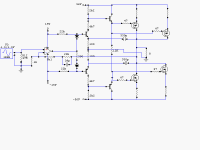
Looks like a CFP using FETs
Should the Vgs +Rs be fed from the Vce of the driver?
or from a resistor in the collector supply of the driver?
How does the VAS determine it's voltage gain? There is no feedback resistor, just a 330p cap. Or is it 4k7/100r? Seems a bit large @ times 47.
Looks like a CFP using FETs
Should the Vgs +Rs be fed from the Vce of the driver?
or from a resistor in the collector supply of the driver?
How does the VAS determine it's voltage gain? There is no feedback resistor, just a 330p cap. Or is it 4k7/100r? Seems a bit large @ times 47.
Simplest class B Amplifier Post #1
Anyone has a simple Class B Amplifier ?
http://www.angelfire.com/ab3/mjramp/amp7.html
Anyone has a simple Class B Amplifier ?
http://www.angelfire.com/ab3/mjramp/amp7.html
Anyone has a simple Class B Amplifier ?
Here, they don't come any simpler than this. Here is part of the audio strip for a longwave receiver I designed and built awhile ago. Pay attention to the final that is connected to the active CW filter.
Works just great for this application. Of course, as for audio quality:
Then, again, high fidelity is neither needed nor desireable in this application.
Edit: Forgot a decimal point. The emitter resistors are 1.0/1.0W, not 10 ohms.
Attachments

Here's a design of great simplicity that I've used in a lot of projects when I needed a quick amplifier.
If you like, I can show you one with even more simplicity that uses three transistors, however, it's nowhere near as nice as the one I've shown here.
(NOTE) The input cap is 2.2µF. I guess if you want a better low roloff you could put 22µF lol.
If you like, I can show you one with even more simplicity that uses three transistors, however, it's nowhere near as nice as the one I've shown here.
(NOTE) The input cap is 2.2µF. I guess if you want a better low roloff you could put 22µF lol.
Attachments
Lol, the PNP transistor in the push-pull output stage on that CW radio amplifier is in backwards.
Yeah, I have to redraw that someday. Anyway, that is not how I built it. It's two complementaries.
By changing that amplifier to work with negative global feedback, it would be not bad.
Wouldn't do much good for what it's used for. The total gain of the entire audio strip is 120db(v). Since this is a TRF design, that's where all the gain comes from. So to add global feedback, and maintain the gain, the open loop gain would have to be even greater, and for a useage where fidelity isn't necessary. Almost all longwave work is CW, and so all it has to do is go: "beep, beep". The DBM also will cause the same sort of distortion on AM that you'd get with SSB. So I designed for stability, which I've got (exception: open input, then you get a 2.5KHz oscillation) and as little tendency for microphonics as possible. It does what it was meant to do.
Edit: Here's a corrected schematic.
Attachments
Hi Andrew T,
I don't follow you're comments. Rest assured everything is in the right place and it will deliver serious power at low THD. the FETS are driven from the low output Z complementary EF and the the predrivers all in a local capacitative local loop to rolloff gain to unity at VHF. The main (global) FBloop is 22K//39p=5K1 to the 1K
at the chip input. All BJT's are BC546/556. DC coupled.
Miles Prower: I understand what you're saying. I just mentioned global feedback as in the last amplifier stage there because it would improve the performance for audio listening.
I am an amateur radio operator and I know you don't need/want good fidelity for listening on CW.")
I am an amateur radio operator and I know you don't need/want good fidelity for listening on CW.
OK, Duo, I see what you're saying. I thought you meant global feedback around the entire audio strip. As for the PA and driver, usually it would be best to take the feedback for the op-amp from the output. I simply didn't do it. Regardless, you're not going to get outstanding performance with simple, 741-type op-amps anyway. 
For whatever the original poster wanted to do, I would endorse that mod. Still, he wanted "simple", and I gave that to him.
For whatever the original poster wanted to do, I would endorse that mod. Still, he wanted "simple", and I gave that to him.
- Status
- This old topic is closed. If you want to reopen this topic, contact a moderator using the "Report Post" button.
- Home
- Amplifiers
- Solid State
- Simplest class B Amplifier