mod_evil said:Hi friends, he necessite a simple amplifier because in rio de janeiro, we arent found a diverse components.
Portuguese version;
Olá amigos, ele necessita de um simples amplificador, porque aqui no rio de janeiro, nós não achamos diversos componentes"
Thanks for the post. I have the book: "Designing Power Amplifier and Hi Quality Amplifier"
It's grate, but i want a more amplifier base.
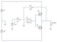
If you want simple, then they don't come any simpler than this one. One op-amp, two MOSFETs and two resistors; just five components for a complete amp (best to use at least two 100nF supply bypass capacitors too, although it is often possible to get away without them depending on exact component choices and layout). I often throw this one together on a breadboard for testing purposes.
Use lateral MOSFETs for lower Vgs. Yes, crossover distortion will stil be high with no biasing at all, but it's surprising just how low it can be with a good fast op-amp. Certainly good enough for non-critical applications and it can be all but unnoticable at high output powers. For high output power use an op-amp like OPA445, for up to +/-45V supply, or thereabouts.
Minor increases in complexity can yield improvements. For instance, a single resistor from the op-amp output to the MOSFET sources will partially compensate for crossover distortion by allowing the op-amp to supply the first few mA of current to the load. A high output current op-amp helps with that. Alternatively, for slightly more complexity, a few diodes and a couple of resistors can bias the output stage into class AB.
Attachments
Mr Evil said:If you want simple, then they don't come any simpler than this one. One op-amp, two MOSFETs and two resistors; just five components for a complete amp (best to use at least two 100nF supply bypass capacitors too, although it is often possible to get away without them depending on exact component choices and layout). I often throw this one together on a breadboard for testing purposes.
Use lateral MOSFETs for lower Vgs. Yes, crossover distortion will stil be high with no biasing at all, but it's surprising just how low it can be with a good fast op-amp. Certainly good enough for non-critical applications and it can be all but unnoticable at high output powers. For high output power use an op-amp like OPA445, for up to +/-45V supply, or thereabouts.
Minor increases in complexity can yield improvements. For instance, a single resistor from the op-amp output to the MOSFET sources will partially compensate for crossover distortion by allowing the op-amp to supply the first few mA of current to the load. A high output current op-amp helps with that. Alternatively, for slightly more complexity, a few diodes and a couple of resistors can bias the output stage into class AB.
So good and simple this amplifier. To decrease the crossover distortion, can i put a 1.2V bias in gate of MOSFETs ?
For the MOSFET can i use the IRF640 ?
I am using the Circuit Maker program to test circuits. is it a good program ?
1.2V is about right for lateral MOSFETs. You'll want to set it so that quiescent current anything up to about 100mA. Less gives more efficiency, more gives lower distortion.PicancoNet said:So good and simple this amplifier. To decrease the crossover distortion, can i put a 1.2V bias in gate of MOSFETs ?
You could (plus its complement for the P-channel). Being a vertical MOSFET you will need a lot higher bias voltage, plus you need to ensure thermal stability via source resistors and thermally coupled Vbe multiplier.PicancoNet said:For the MOSFET can i use the IRF640 ?
Mr Evil said:
1.2V is about right for lateral MOSFETs. You'll want to set it so that quiescent current anything up to about 100mA. Less gives more efficiency, more gives lower distortion.
You could (plus its complement for the P-channel). Being a vertical MOSFET you will need a lot higher bias voltage, plus you need to ensure thermal stability via source resistors and thermally coupled Vbe multiplier.
I made this circuit. Is it realy can give 50W at 2V@4ohms in input ?
Attachments
Hi,
you just blew up your 741 putting 80v across it.
you have to limit the Vrail to the same voltage as your opamp requirements.
OR use a voltage amplifier between the opamp and the output stage.
That one by Amplifier guru does that, even though I still can't understand it.
you just blew up your 741 putting 80v across it.
you have to limit the Vrail to the same voltage as your opamp requirements.
OR use a voltage amplifier between the opamp and the output stage.
That one by Amplifier guru does that, even though I still can't understand it.
AndrewT said:Hi,
you just blew up your 741 putting 80v across it.
you have to limit the Vrail to the same voltage as your opamp requirements.
OR use a voltage amplifier between the opamp and the output stage.
That one by Amplifier guru does that, even though I still can't understand it.
I put the 741 only to reference. It is a hypotetic Op Amp
I expect that would work ok.PicancoNet said:I made this circuit. Is it realy can give 50W at 2V@4ohms in input ?
Simple is beautiful tooUpupa Epops said:Why are you all still fascinated by some simply ***** ? Wake up guys, now is the time, when useable transistors cost only 5 cents !Simply Zen, simply GC, simply ... Beauty is in complicated connections, only with them you can make right amp.
Ok, so most of these amps aren't going to give the greatest quality, but they are useful. Like I said, I find the one I posted is useful when I need a quick test amp. Simple amps are also the best place to start learning.Simple CAN also sound good.
see:
http://www.diyaudio.com/forums/showthread.php?s=&threadid=33912
Not much more complicated, very adaptable (I've used it with IRF devices). I also made a version using 2 green LEDs in place of the Vbe multiplier. No Global Feedback, only local. I would add Gate stopper resistors tho. Especially with lateral Mosfets. If the Output seems to be too hot for what its doing, then its oscillating and the gate stoppers will stop this. SK1058/SJ162 seem to need higer values for the stoppers. 220 should be fine for IRF Devices and 470 for SK1529/SJ200 seems OK. The Cap between the Opamp and the Output is probably not necessary, just a little protection.
-D.
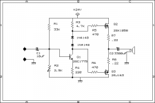
Here's a bare bones Basic AB circuit. R2 sets the bias for the amp and should be set so that 1/2 the supply voltage (~12V) is seen between the + side of C2 and Ground.
No Global Feedback and 2V should send it to clipping. Will post Distortion Spectrum Later.
1V in will swing about 13Vpp. I figgure that is about 20W into 8Ohms with a 1K source impeadance.
C1's polarity is reversed. sorry.
No Global Feedback and 2V should send it to clipping. Will post Distortion Spectrum Later.
1V in will swing about 13Vpp. I figgure that is about 20W into 8Ohms with a 1K source impeadance.
C1's polarity is reversed. sorry.
Attachments
Hi Amplifier Guru,
I planted some currents into the circuit & calculated the standing voltages. It seems to indicate that the right level of voltage appears across the CFP 2nd stage.
But all the CFPs I've seen before had a collector resistor on first stage & used the volts drop across the R to generate the driving voltage for the second stage.
Is yours connected to the emitter because of the voltage amplification? or is that a separate issue?
I still think previous circuits with voltage amplification had a local gain loop ireturning to the emitter but your's does not.
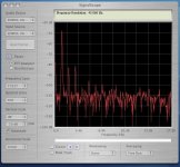
Dozuki said:I did some real measurements on the above amp:
1000 Hz sine input at .66v (1v out of source unloaded)
Unloaded output of amp : 12.7V
Output with 8 Ohm speaker: 10.5V
13 Watts output
Distortion Spectrum in db with 8 Ohm speaker load:
Hello,
What program did u use to made this measurements ?
Quick guess on Amplifierguru's circuit. Is the voltage gain achieved by the first transistor stage, then the second transistor stage is to buffer the the gate drive requirements. The MOSFETs are connected apparantely upside down to instigate an inverting action so that the overall feedback is negative, as the first transistor stage causes an inversion. Also to facilitate rail-to-rail swing.
your calculator needs new batteries.
13Vpp is 2.6W into 8R
10.5Vpk is 6.9W into 8R.
Is that a typo 2sj163?
can this amp really swing to within 1.5v of the rails with that drive circuit?
2.6W and 6.9W RMS, yes (although 13 Vpp would be 10.6W RMS). I guess I should have clearified that I was measuring Peak Voltages and Peak Power, not RMS.
I=E/R and W=I*E in which case
10.5e/8r=1.3125i, 1.3125i*10.5e=13.78 Watts Peak to Peak
Yes, that's a typo, should be 2sj162
And since I was measuring Peak to Peak, the amp stays within 5 volts of the positive rail and 5 volts of ground with about .66v input.
What program did u use to made this measurements ?
An Oscilloscope that shows voltages
and Signal Scope for the distortion specs.
With the circuit built on a breadboard.
Edited Schematic, and input cap is correct:
Attachments

- Status
- This old topic is closed. If you want to reopen this topic, contact a moderator using the "Report Post" button.
- Home
- Amplifiers
- Solid State
- Simplest class B Amplifier