I have an SWR sm-400 bass amp (same power circuit as in mikebarg's thread in May), which has the TO-3 2SD424's. After 1993 they discontinued the sm-400 in favor of the 400s, which should have Sanken transistors: 2SC3264 for outputs.
I've been thinking about upgrading to the Sanken circuit after one channel fried (see my intro thread 5/29). The circuit changes are rather minor - it appears that they opened up the upper bandwidth a little since the 2SC3264 will go to something like 20 MHz over the 424's 6 MHz. I played through a 400s and it sounded damgood! Plus it seems to me that the Sanken T's would be much more reliable.
However... The Sanken is an MT-200 casing, and (I think) it's BCE pinout makes an awkward situation.
Does anyone have an SWR amp with the Sanken transistors? Any info on how the T's are mounted on the heat sinks, etc. would be of help. I don't know if perhaps the board layout was redesigned. Any other thoughts on this idea?
I have rebuilt and owned several SWR amps, I recently rebuilt a WM-300 and a WM-2004 and i currently own a SM-900 all with sanken transistors, and all use the same circuit. in fact. SWR only designed ONE schematic and all of the amplifiers have been one variation or another of the same N-Channel power amp design.
I have schematics of just about all the models (Thanks Enzo!) But i have not yet worked on an older model that had the TO-3 cases. im sure major heatsink changes would be needed as well as board mods.
Many people feel that a large part of the SWR sound quality comes from the Snaken transistors. I admit i do like my SWR's better then the Hartke and Ampeg amps i have owned and played through. I have not yet had a chance to check out an Eden amp just yet, but my SM-900 is pretty dang close to the ultimate amp for me.
The only 2 things it doesnt have that i miss and wish it did have are the Speaker on/off switch and a front power switch. other then that the thing is great!
Zc
Glad to hear from you. On my amp, the heat sink block seats on four TO-3 sockets soldered to the board, and the transistors mount in from the side opposite the board through holes in the HS. Can you tell me in general, or specifically, how the Sanken's mount?
Also, have you bought any of those transistors within the US? I'm currently checking with MATelectronics who lists 2SC3264 for $2.48 at the 10 quantity.
Also, have you bought any of those transistors within the US? I'm currently checking with MATelectronics who lists 2SC3264 for $2.48 at the 10 quantity.
I buy my Sankens through B&D Elelectronics.
http://www.bdent.com
I have purchased about 8 so far and i did some pretty extensive testing with the first batch to make sure they were real. everything looked like they checked out. i built a test circuit and they all passed so i put them in the first amp and all was good. i ran the amp at full power and 1/3 power for and hour each and everything checked out fine.
the WM-300 and 2004 have a solid finned heatsink that mounts on the back of the case. the MT-200's are bent up and mount flat to the inside of the heatsink. the PC board mounts on standoffs above the MT-200's. PITA to get the board out of those amps. I found that the plastic stand off's are about 1/8" too tall and that the BIAS transistor just barley makes it to the board. i trim a bit off the stand offs to get the board closer so the transistor leads will extend through the PCB with just bit to spare and solder onto.
The leads of the transistor are stretched so tight that it can cause the transistor to fail internally. I had one amp that would work fine 75% of the time, but one in a while it would blow the fuse instanly when you hit the switch. the BIAS transitor would go open internally and if you wiggled the leads, would intermittantly make connection inside. that was a bugger to figure out!
My SM-900 has 2 amp boards/heatsinks in a tunnel inside, still same arraingment sort of.
I have some photos of the rebuild.
Zc
Attachments
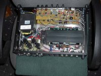
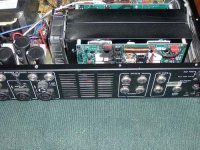
Hey! Thanks, zero cool. I really appreciate the pictures. I think the "wind tunnel" arrangement is interesting. They sure made some significant changes from the old 400 that I have. I have a hunch that the old TO-3 products weren't the most reliable. There is not even a fan! If you're really curious, I can post some photos of the sink arrangement on my 400.
Yeah i would love to see the inside of a 400.
Now rememeber this is just the way the SM-900 works because of the dual amplifiers inside for biamping or stereo operation.
The 2004, 4004, WM-300 and just about every other model just uses 1 heatsink mounted to the rear with no fan or anything. same circuit as this but only one sink etc.
Zc
Now rememeber this is just the way the SM-900 works because of the dual amplifiers inside for biamping or stereo operation.
The 2004, 4004, WM-300 and just about every other model just uses 1 heatsink mounted to the rear with no fan or anything. same circuit as this but only one sink etc.
Zc
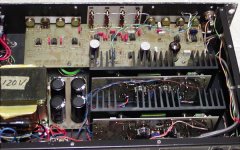
 as there are no 1.5 ohm resistors on the output filters. It's stereo and bridgeable. No soldermask or screenprint on the boards! There were no connectors inside, all straght-wired.
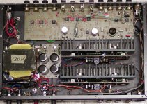
Yeah you would have to do massive changes to use the MT-200 devices.
What you could do, is buy the ST-800 power amp. which is essentially a SM-900 amp section only. these sell for $300 or less and remove the amp modules and swap them into your amp. but, then again. why go through all that hassle. fix your 400, sell it and then buy one of the newer amps that already have the MT-200's in there.
I see from the photo's that the regulator issue i have with my newer amp is a carry over from the older models. your amp has the same circuit basics going on there. only mine they stacked two 5 watt resistors on top of each other piggy back style with out any additional support.
I am thinking about making some Filter bank circuit boards that incorporate fuses and active regulation and sell them and a upgrade. i need to make at least 4 boards at a time to be cost effective anyway so... Just an idea.
Zc
Hey zerocool.
Yea, once I saw the 900 I was thinking along those lines. The ST-800 might be a good idea. I'll probably check e-bay for a broken one! But the power supply on 400 is +/- 60 v and I think the 800/900 is 75 v, among a few other minor things.
As for the preamp lines, I was somewhat concerned myself when I saw mine. Each line has two R's in series (twisted together mounted through two holes) and board had turned dark around these. They look like they're only a few watts.
Workhorse:
I have schematics of the 900 which are freely given from Fender. They are actually .pdf files, too large to post here. I will try going to your website.
Hi ADROME,
Could you plz email them to me....
mail to: info@workhorsetechnologiesindia.com
regards,
Kanwar
Could you plz email them to me....
mail to: info@workhorsetechnologiesindia.com
regards,
Kanwar
One other alternative: You can keep the TO3 layout and use MJ15024 in place of the 424s. Several OEMs have done this, and I have had success with this sub in commercial appplications. As an authorized SWR repair center, I wouldn't hesitate to do the sub.
Allied is a reasonable source for the 15024, and for the rest of the MJ15xxx family. Allied recently dropped their minimum order policy too.
I am not sure the differences in bandwidth over 6MHz makes much difference to audio. I think the staability network rolls off a bit lower than that.
Allied is a reasonable source for the 15024, and for the rest of the MJ15xxx family. Allied recently dropped their minimum order policy too.
I am not sure the differences in bandwidth over 6MHz makes much difference to audio. I think the staability network rolls off a bit lower than that.
Hello Enzo,
Yes, this is what I had tried to say. For stability the upper F bandwidth limit is controlled to much, much lower than those MHz figures. But since the Sanken's can go higher it would be safe to correspondingly increase the BW limit by redesign.
Actually, I have not tried to correlate the changes in the B-C feedback caps with the transistor characteristics, or done any serious calculations of the total frequency response.
Thanks for the suggestion. I don't have any data on the 15024, what advantages might it have over the 424?
- Status
- This old topic is closed. If you want to reopen this topic, contact a moderator using the "Report Post" button.
- Home
- Amplifiers
- Solid State
- SWR amps anyone?