Hi CK
Without C42-45 the four triodes should still not start to roll off at about 25kHz, so are you using a low impedance source with a high quality input coaxial lead ?
For high fidelity it is *essential* that your source has a low output impedance to drive against feeder cable and amplifier input capacitance.
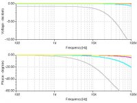
I have graphed the response of four possible source/cable responses.
Yellow; 100 ohm source plus two metres of miniature single core into 100k.
Aqua; 1k ohm source plus two metres of miniature single core into 100k.
Fuschia; 1k ohm source plus two metres of premium audio cable into 100k.
Silver; 10k ohm source plus two metres of miniature single core into 100k.
Could this be where your 40 degrees of roll-off is coming from ?
Cheers ......... Graham.
Without C42-45 the four triodes should still not start to roll off at about 25kHz, so are you using a low impedance source with a high quality input coaxial lead ?
For high fidelity it is *essential* that your source has a low output impedance to drive against feeder cable and amplifier input capacitance.
I have graphed the response of four possible source/cable responses.
Yellow; 100 ohm source plus two metres of miniature single core into 100k.
Aqua; 1k ohm source plus two metres of miniature single core into 100k.
Fuschia; 1k ohm source plus two metres of premium audio cable into 100k.
Silver; 10k ohm source plus two metres of miniature single core into 100k.
Could this be where your 40 degrees of roll-off is coming from ?
Cheers ......... Graham.
Attachments
Seems the silver cure with a huge roll off. In my case I only connect the signal generator output direct to the AMP input. The signal generator is a general one (kit product) about 300HKD.
Nevertheless, it connect to my Matissa DIY Pre-AMP (such PCB made in China) would not happen this sympton. It can generate a very good output w/o phase shift even up to 20KHz square wave input.
Perhaps, the input stage PCB design and etchant by myshelf. Which is double layer supply associate with the gain circuit. PCM both sides placed GND plane. :>
Would you like to help answer my pervious posted questions about the DC supply in output stage and the sound clipping reason ?
Welcome to all your feed back .
Hi CK
Where did this circuit come from, and was it ever proven ?
My tube books are in the roofspace, so;
Are these triodes hi-mu/high anode resistance types, because hi-mu triodes having a high anode resistance and used with high value anode resistors (160k resistor per triode and say just 1.5mA current) really will degrade your high frequency response ?
For hi-fi I would not go beyond medium anode resistance with a maximum 22k anode resistor per triode, though here the 5751 usage/performance might be intentional.
I don't like the capacitor coupling between the tubes and the mosfet bias chain. There is a substantial risk for the semiconductor circuitry to cause a partial and unequal rectification of waveform when driven to clipping. The triodes are capable of conducting more than the emitter resistors, and thus large amplitude tonebursts could cause an alternating zero level shift.
I trust that you have the 47 ohm resistor connected between the Q18 and Q19 sources, and not between Q18 source and output. This is hard to make out on the circuit copy.
Cheers ......... Graham.

I have got it in few years ago at one of the HiFi column. Who also expressed no experience on it. Actually, this circuit is CJ¡¦s EV2000 you can still find in their WEB. Where they explore it is same to the circuit behaviour. But what I got may not their final version or somewhat the value of components may changed. As a result I made it really without major problem.
5751 amplification factors in a range of 55 ¡V 85. Detail can by obtained by an attachment.
Actually, R51=47ohm connected between Q18 and Q19 source, you may be interfaced by such fuzzy picture . A second point you see a 4 x 160k ohm anode resistors are in parallel therefore the resultant resistant is 40k ohm. Did you claim its resultant need to change as 22k ohm ? (The circuit PDF version will send to you by mail separately.)
DC supply at point B+ = 53V , D+ = 53V , E+ = 26V and Anode = 390V these are my personal used. I did not exactly follow the DC provision by the circuit, just change the zener reference voltage value. So you can find B+ is 80V provided. I through B+ will too high (110VDC) when I made the secondary output in series.
Attachments
I exactly follow the schematic use 4 x 160k ohm (R31 - R34)parelleled together connect to the 4 single triodes they are shorted together.
Is it too big ? But what value should be used when 90vAC swing on the input stage ? It there R31-R34 and R27-R30 values need to be changed based on this requirement.
I intent to increase the output stage supply DC up to 80VDC.
Is it too big ? But what value should be used when 90vAC swing on the input stage ? It there R31-R34 and R27-R30 values need to be changed based on this requirement.
I intent to increase the output stage supply DC up to 80VDC.
- Status
- This old topic is closed. If you want to reopen this topic, contact a moderator using the "Report Post" button.
- Home
- Amplifiers
- Solid State
- About my hybrid nofeedback AMP