I've checked out many amplifier designs, and especially the PSU designs. But there's a big difference in the recommendation for the power of the transformer (sometimes it varies about 2 or 3 times for the same output power).
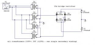
So, I would like to ask you what class AB amplifier (stereo, maybe 4 amps bridged) (?? watts) I can build with 8 transformers of 120 VA (1x30~34V). The transformers can be placed in parallel without any problem (because that's what I'm doing right now). The amount of capacity is no problem...
The load will be an 8 ohm speaker. I normal conditions the amp would play 2 x 100W (rms) into 8 ohm load, but what is the limit I can push the amp to (without blowing any transformer) when we need some more power? (in this case quality of sound isn't that important)
I would like to protect those transformers against too high currents with fuses, what fuses should I use there the max. current in the secondary winding is 4A??
HB.

Nelson,
do you mean that I can handle that with four 120VA transformers with only one secondary winding (maybe this wasn't clear with my explanation above).
so I've build this supply (and have the components for the second one). It would be fantastic if I can drive a 4 ohm load with this psu.
EDIT: the 1khz of the mains isn't correct of course: must be 50Hz
best regards,
HB.
Attachments
Magic amps
Well they must be using magic
\Jens
skaara said:Isnt that big difference? Ive seen some other amps that can provide 160-180w at this voltage, why is this one an exception?
Well they must be using magic
\Jens
Jens,
maybe a good idea, although I didn't have problems with that single bridge. I'm thinking about using a bridge for each two transformers in series, and then connect the outputs in parallel.
do you think I can drive a 4 ohm load with this psu or not? Because I'm a little confused about what I've read about the psu's in the articles I've got here...
HB.
Hello,
Here is an example of one other way.
Best regards,
Kristijan Kljucaric
http://web.vip.hr/pcb-design.vip
Here is an example of one other way.
Best regards,
Kristijan Kljucaric
http://web.vip.hr/pcb-design.vip
Attachments
to hugobross
To drive a four ohm load continuesly it will problably not be enough, but if you have a good amount of caps, I'm sure the result will be ok.
The project I'm making at the moment the unloaded rails are +-55 V, but they drop to about 45 at 200 W into 4 ohms.
There is a thread with pictures here.
http://diyaudio.com/forums/showthread.php?s=&threadid=4091
Hope it will work out for you
I still think seperate bridges will be best
\Jens
thanks,
Jens, your amp looks wonderful!!!
first, I will make 2 boards of the prototype I've build recently. Later I will add two extra boards (and extra caps) for bridging.
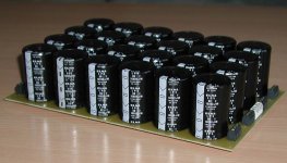
I guess the amp will weight about 35 kg, due to the 8 transformers. I know it's heavy, but I've got to clean up all the components laying around here
best regards,
HB.
Jens, your amp looks wonderful!!!
first, I will make 2 boards of the prototype I've build recently. Later I will add two extra boards (and extra caps) for bridging.
I guess the amp will weight about 35 kg, due to the 8 transformers. I know it's heavy, but I've got to clean up all the components laying around here
best regards,
HB.
kristijan-k said:Hello,
Here is an example of one other way.
(two bridges)
Best regards,
Kristijan Kljucaric
http://web.vip.hr/pcb-design.vip
This is better imho. This way you can make two completely separated psus. You can then run the two returns (ground points) to a star point together with the speaker return. Makes the grounding (and sound) cleaner for the same price.
Jan Didden
Jens,
It's a long time ago i did that measurement, but I remember the differences where very low.
nice picture, but I would never use that kind of connectors anymore you use over there, it's good to make once a connenction, otherwise your traces on the pcb will suffer!!
HB.
It's a long time ago i did that measurement, but I remember the differences where very low.
nice picture, but I would never use that kind of connectors anymore you use over there, it's good to make once a connenction, otherwise your traces on the pcb will suffer!!
HB.
I've used the same type of connectors for the input of DC-controlled dimmers in my own made light-controller (a previous project of mine - looks pretty nice and works very well; I'll post it in the future...). I think I rewired the dimmers about 4 times, and I had lot's of traces broken (the pcb's were of high quality), or solder pins that are 'pulled' out the solder tin and so making bad contacts. The problem with this connectors is that only the pins hold the connector to the pcb and not some extra screws or something else. So each time you turn on the screws you're pcb or solder tin suffers a lot!!!
best regards,
HB.
best regards,
HB.
LeachAmp power output
There's a couple reasons, and I suspect that this is more of a norm than an exception.
The first is PSU droop under load. The actual rail voltages are closer to +-50VDC under full load. The second is the Triple-Darlington output stage, which drops about 3.5V from predriver input to speaker output at full power into 8 ohms. The third is the decoupling of the class A stages through the 82ohm resistors (R32 and R33). The voltage drop across these resistors is about 1V. Next is the 390 (360 plus 30) ohm emitter resistors on the voltage gain (Q12 and Q13), lowering the voltage another ~1.5V. Add it all up and you get about a 6V drop, or essentially 44Vpeak output with "perfect" +-50VDC rails. 44Vpeak = 121W/8, so 125W/8 is about correct for the LeachAmp.
Cheers,
Mark Broker
skaara said:+-40v = 90w
+-58v = 120w
Isnt that big difference? Ive seen some other amps that can provide 160-180w at this voltage, why is this one an exception?
There's a couple reasons, and I suspect that this is more of a norm than an exception.
The first is PSU droop under load. The actual rail voltages are closer to +-50VDC under full load. The second is the Triple-Darlington output stage, which drops about 3.5V from predriver input to speaker output at full power into 8 ohms. The third is the decoupling of the class A stages through the 82ohm resistors (R32 and R33). The voltage drop across these resistors is about 1V. Next is the 390 (360 plus 30) ohm emitter resistors on the voltage gain (Q12 and Q13), lowering the voltage another ~1.5V. Add it all up and you get about a 6V drop, or essentially 44Vpeak output with "perfect" +-50VDC rails. 44Vpeak = 121W/8, so 125W/8 is about correct for the LeachAmp.
Cheers,
Mark Broker
what about fusing the whole thing?
Hi again,
I've just mounted all the transformers and the caps in my case, it weights heavy!!
But how do I have to fuse the whole thing(1 psu with 4 transformers / channel), I was thinking about the normal way, two fuses (pos. and negative rail) and one fuse at the primary. But will that primary fuse provide enough protection when one of the 4 (or 2)bridges is shorted (because that one is rated at the current of four transformers).
Or can I place the rail fuses before the rectifiers? probably not because of the turn on current of the psu...
or maybe using more primary fuses?
HB.
- Status
- This old topic is closed. If you want to reopen this topic, contact a moderator using the "Report Post" button.
- Home
- Amplifiers
- Solid State
- psu question n° ???