HELLO!
I need help to solve a problem.
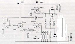
The joint principle schematic is about an hybrid power amplifier made by two stages:
- all voltage gain: vaccum tubes
- current gain: BJT.
The "rest" current is regulated by diodes, as you can see.
Now I need a solution to enter from the tubes stage to the bjt stage but please first read the following points:
- The first solution will be to enter by two capacitor on points (equal) A and B.
- The second solution will be to enter by only one capacitor, for example on point C.
This solution is not very good because the signal will pass through the diodes, with some non linearity. But of course it works.
NOW, the question is (number three):
1) I don't want to use capacitors to couple the two stages.
2) I don't want to use transformer to couple the two stages.
I already solve this problem!
Infact I have used a special vacuum tube stage, with a dual voltage, that comes out only with the signal and NO dc voltage.
In this case I can direct couple the vacuum tube stage to the BJT stage, entered on poit C, without capacitor... OK! It works.
BUT BUT...
as I already said, the non linearity of diodes makes the sound bad, especially low frequencies.
SO and however, I don't want to enter on point C but in the same time on points A and B.
BUT...
in the BJT schematic, I CANNOT JOIN POINTS A AND B OTHERWISE I WILL BURN THE AMPLIFIER!!!
SO WHO HAVE THE SOLUTION TO THE PROBLEM WITH PLEASE A LITTLE SCHEMATIC TO EXPLAIN ME BETTER??
I think is so simple that I cannot see it.
Thank you very much, sorry for my english, if anything is not clear please just ask.
G.M.
I need help to solve a problem.
The joint principle schematic is about an hybrid power amplifier made by two stages:
- all voltage gain: vaccum tubes
- current gain: BJT.
The "rest" current is regulated by diodes, as you can see.
Now I need a solution to enter from the tubes stage to the bjt stage but please first read the following points:
- The first solution will be to enter by two capacitor on points (equal) A and B.
- The second solution will be to enter by only one capacitor, for example on point C.
This solution is not very good because the signal will pass through the diodes, with some non linearity. But of course it works.
NOW, the question is (number three):
1) I don't want to use capacitors to couple the two stages.
2) I don't want to use transformer to couple the two stages.
I already solve this problem!
Infact I have used a special vacuum tube stage, with a dual voltage, that comes out only with the signal and NO dc voltage.
In this case I can direct couple the vacuum tube stage to the BJT stage, entered on poit C, without capacitor... OK! It works.
BUT BUT...
as I already said, the non linearity of diodes makes the sound bad, especially low frequencies.
SO and however, I don't want to enter on point C but in the same time on points A and B.
BUT...
in the BJT schematic, I CANNOT JOIN POINTS A AND B OTHERWISE I WILL BURN THE AMPLIFIER!!!
SO WHO HAVE THE SOLUTION TO THE PROBLEM WITH PLEASE A LITTLE SCHEMATIC TO EXPLAIN ME BETTER??
I think is so simple that I cannot see it.
Thank you very much, sorry for my english, if anything is not clear please just ask.
G.M.
Attachments
It would help if you post the schematic of the tube driver stage... it may be suitable for putting the bias voltage generator in series with it's tube(s)...
Otherwise, here are some pointers:
1) Your bias (standing current generator) is potentially thermally unstable (you do not give values of the resistors so I cannot be sure), if the resistors are small in value, you cannot compensate 6 diode drops (Vbe of your tripple darlington) with 3 diodes (hopefully they are on the heatsink with the output devices!). Use a Vbe multiplier instead, or even two complementary Vbe multipliers (divide the bias voltage into two parts), then inject signal in the middle, which would be similar to your point C. The only way to ensure the Vbe multipliers do not act as an extra nonoinear stage, is to bypass them with a suitable capacitor or capacitors.
2) If you join points A and B your bias will drop to zero - and unless your amplier is unstable, absolutely nothing bad will happen except for very high distortion.
3) Your tripple darlington makes all 3 stages work in class B which generates excessive distortion. Your transistors can turn on quickly but not turn off as you do not provide any way of the excess base charge to escape (i.e. a resistor between base and output of the amp or between emitters of transistors in each stage). If this stage ever goes into oscilation, it will likely destroy itself.
4) Your bias generator is fed from resistors conencted to + and - supply rails of the BJT portion of the amp. This quite unnecesairly load the preceeding tube stage, which, unless you are using a large triode or pentode, increases it's didtortion. Using current sources instead would be a better deal, and also prevent the idle current from being dependant on rail voltage. In your schematic bias current is heavily dependant on rail to rail voltage as any change there produces a varying voltage on the resistors in series with the diodes between the bases of the BJTs. Bias is also dependant on the input signal (thoug this is less of a problem) since that also changes the current through the same resistors.
anatech said:Hi gianmaria,
How do you deal with the offset before the tubes are wared up and stable? What happens if there is DC drift? I can't see your tube stage, but I can't imagine getting around those shortcomings. You need a coupling cap.
-Chris
Bot if you have a DC servo setup. If so, it needs to be fed from the output of the amp, not of the tube stage. DC servo is not that much more difficult for tubes than for silicon...
Hi ilimzn,
If the tubes are not conducting yet, your DC offset = supply voltage. A couple hundred volts anyhow. There is no DC servo that will help in this situation. Same for a bad heater contact. Bye Bye speaker(s).
Direct coupling a tube stage to a solid state output stage is never a particularly intelligent idea. Sorry.
-Chris
It is quite typical (and of course expected) that the DC servo is coupled with output protection, which disconnects the speakers until the proper operating conditions are reached.
There are several direct coupled amps that use a similar approach, the most popular was produced in thousands of pieces - the Luxman LV-103/4/5(u) series (too bad the direct coupling is one of it's few virtues...)
Of course, if you do not want to have any series elements on the output, it is not at all difficult to disconnect the driving signal until proper conditions are present (again, you use the output of the DC servo to sense for this).
Of course, if you want to keep it as simple as possible and avoid any switching of the audio signal, (and there really is no reason why this would be a lesser approach), you can always capacitor couple as you say.
Okay, the Luxman units are not the same topolgy as gianmaria is thinking from the sounds of things. I am very familiar with these units. They do incorporate a SS front end, the tubes are not run from extremely high voltage (high enough I guess). The tubes are almost in circuit as a curiousity. I do agree they are nice sounding amplifiers.
I fixed many of these over the years and under warranty.
I would like to see what gianmaria is thinking about for the rest of the circuit. Otherwise there is no helpful info I can give.
-Chris
I fixed many of these over the years and under warranty.
I would like to see what gianmaria is thinking about for the rest of the circuit. Otherwise there is no helpful info I can give.
-Chris
Hi to everybody and thank you all.
Here you have a less principle (for the BJT stage) and a principle schematic for the tubes stage I'm using at the moment.
As I repeat, now I'm entering from the tubes stage to the BJT stage on point C of the circuit, of course without any capacitor seen that from the tubes stage we have only AC voltage output (i.e. musical signal).
It works, but I think is not the best solution.
I repeat my question:
I don't want the signal to pass through diodes, but I want it to be connected directly on points A and B, WITHOUT ANY CAPACITOR OR TRASFORMER.
But I cannot join points A and B otherwise the amplifier will work very very bad.
Thank you very much, G.M.
Attachments
anatech said:Okay, the Luxman units are not the same topolgy as gianmaria is thinking from the sounds of things.
I know, but I was thinking more along the lines of their solution to
tube warm-up, which essentially works like a DC protection 'backwards' - it waits until the DC at output is small enough to switch on the speaker. In the mean time, the output stays stuck to one rail, but that really is not a problem as it is disconnected.
...The tubes are almost in circuit as a curiousity...
I would like to see what gianmaria is thinking about for the rest of the circuit. Otherwise there is no helpful info I can give.
The tubes being in circuit was exactly what I was thinking about for Gianmaria.
Looking at his tube stage, it would be of benefit to remove the 56k 1/2W resistors from the output stage, and also cut the connection of the pentode cathode resistors and insert the bias string in it, also reconnect the DC servo from the output of the BJT stage, and finally, use some form of DC detect and a relais to switch off the speakers for any DC at the utput.
Alternatively, if one wanted to avoid the output switching, one could use BJT input stage switching instead. This requires a DPDT reed or similar hihg quality relais. The bias string remains inside the pentode cathode circuit, but is connected to points A and B via resistors (large-ish, several k), let's call them Ra and Rb. The DPDT contacts of the relais are connected so that in the initial position, points A and B are connected to ground of the output supply (through the series resistors Ra and Rb), hence the output has no bias and is switched off. When the DC servo detects that there is sufficiently low DC on the output of the follower, the relais switches over so that Ra and Rb are now short-circuited and points A and B are connected to the bias string directly. For this option, the DC servo must go from the midpoint of the bias diodes.
IT IS STILL NECESSARY to use a capacitor across points A and B (i.e. the diode bias string)!!! but this can now be low voltage, but higher capacitance, and therefore you have a wider choice of quality caps. This will insure that the bias is applied slowly at switch-on, as well as bypass all AC signals so they do not pass through the diodes. I do not know of any other practical way to do this without a capacitor, unless you want to double up the complete input stage (one for each point, A and B), and introduce bias voltage at the input of the DC servo. Even then, any trouble with the tube section is likely to cause disaster, unless you have a capacitor across A and B, with which you are back to the simpler solution.
The pentode follower will also work much better with a constant current source in the cathode (and so will the bias string, for that matter), you can easily obtain current source action by the use of bootstrapping from the BJT output stage, but you need a good quality, fairly high voltage and therefore probably expensive, capacitor.
The problem with this as I see it:
1. The output stage is biased -220VDC until the tubes warm up. Transistor stage is now damaged because of reverse e-b bias as the output supply voltage is less than this.
2. The DC servo will never operate because it got blown up on start up. One input biased to -220VDC also.
This circuit requires a coupling cap between stages to be safe. The circuit also requires protection relays between stages and the speaker output. The DC servo can only be connected once the tubes have stabilised and the offsets are within a safe range. I wouldn't worry about the sound quality of having a coupling cap compared to the rest of the circuit. It would be interesting to see how it sounds.
-Chris
anatech said:The problem with this as I see it:
1. The output stage is biased -220VDC until the tubes warm up. Transistor stage is now damaged because of reverse e-b bias as the output supply voltage is less than this.
You really like to nitpick, don't you
")
Any designer worth their salt will take into account that the driver stage can theoretically swing the full rail difference, which is +-220V (IMHO a slight overkill). Diodes from input to BJT power stage to it's supply rails are absolutely necessary. A coupling cap will not solve this!!!
For idea 1 I proposed (speaker relais) the output stays stuck at approximately -V rail until the tube starts conducting. For idea 2 (BJT input stage relais), the BJT input stage is clamped to ground anyway until tube starts conducting.
2. The DC servo will never operate because it got blown up on start up. One input biased to -220VDC also.
The DC servo will never operate, PERIOD. This is becaus it's missing an input resistor, and I think this is just a drawing error. This resistor would normally be in the hundreds of kiloohms region and actually, most normal OPamps would survive HV application through it due to either deliberately provided protection or parasitic diodes to the substrate, but they may latch up. In other words, it needs an input diode or zener clamp. Again, coupling cap would not help here (though of course, if you have one, you do not need a DC servo).
This circuit requires a coupling cap between stages to be safe. The circuit also requires protection relays between stages and the speaker output. The DC servo can only be connected once the tubes have stabilised and the offsets are within a safe range. I wouldn't worry about the sound quality of having a coupling cap compared to the rest of the circuit. It would be interesting to see how it sounds.
Well, I would agree that would be the simplest solution - but then, the man wanted a circuit without one.
Also, I am not doing a design for him, just giving ideas. Awarenes of startup conditions, overdriving, clipping, etc, and how to provide safe operation of a circuit in these modes should be foremost on the mind of any designer, especially one attempting to design something like this from scratch - which is why I did not include protection circuits and parts which should have been in the circuit regardless of the problem which this thread is trying to explore.
BTW gianmaria's tube circuit has far worse problems, which render the argument of DC vs capacitor coupling very much academic: Even if the DC servo was corrected, it would not work properly.
This is because the DC servo will try to drive the output of the follower to zero, and that can only be more positive than it's input, which is directly coupled to an output of a circuit that cannot drive all the way to zero in the first place.
Without the DC servo, the circuit will still not be able to swing below zero (obviously) but if the output was capacitor coupled to the BJT part, it may work. However, then it does not need the -220V rail, as well as one triode. Even with negative rails (input would be referenced to the negative rail - which is a problem - and capacitor coupled) a working DC servo, it may not need the extra triode - it's simpler to inject the DC servo output into the cathode circuit of the input triode.
Why use a SRPP only to drive a follower? A current source would be a better idea, which can be had for the price of one capacitor and one resistor - and one less triode - by the use of bootstrapping off of the follower output.
Hi ilimzn,
I was not responding to your comments , but rather just making some observations. I am very familiar with the hybrid idea having designed and built a few. That and repairing both Counterpoint and Luxman under warranty.
Yes, you can clamp the offending voltages. But why start behind the 8-ball? I would capacitor couple the two stages and use a relay to short the bipolar side to ground (this charges the cap). When the relay releases the line there should be no differential (read spike or pop in the output). You only need to worry about the DC potential of the output stage, not the tube stages.
I'd like to see where this goes design wise. I still think the no capacitor idea just complicates things needlessly.
-Chris
I was not responding to your comments
, but rather just making some observations. I am very familiar with the hybrid idea having designed and built a few. That and repairing both Counterpoint and Luxman under warranty.Yes, you can clamp the offending voltages. But why start behind the 8-ball? I would capacitor couple the two stages and use a relay to short the bipolar side to ground (this charges the cap). When the relay releases the line there should be no differential (read spike or pop in the output). You only need to worry about the DC potential of the output stage, not the tube stages.
I'd like to see where this goes design wise. I still think the no capacitor idea just complicates things needlessly.
-Chris
Hi ilimzn,
We were posting at the same time. The opamp is driving the inverting input of a diff pair (V1 V2) that is referenced to ground. I can't see how V2 is expected to work properly with almost no voltage across it. I see this as an embryonic design at present. Design has issues.
-Chris
We were posting at the same time. The opamp is driving the inverting input of a diff pair (V1 V2) that is referenced to ground. I can't see how V2 is expected to work properly with almost no voltage across it. I see this as an embryonic design at present. Design has issues.
-Chris
anatech said:Hi ilimzn,
I was not responding to your comments
I know, I believe we corresponded in a thread regarding the Counterpoint SA100.
Yes, you can clamp the offending voltages. But why start behind the 8-ball? I would capacitor couple the two stages and use a relay to short the bipolar side to ground (this charges the cap). When the relay releases the line there should be no differential (read spike or pop in the output). You only need to worry about the DC potential of the output stage, not the tube stages.
As I said, I would agree - though, you still need to clamp the input to the BJTs as overdriving the tube stage will reverse-bias the B-E junction of the BJTs to a potentially dangerous level, with or without a cap.
Once that is in the picture, some advantages of DC coupling rear their head (the cost and complication of it is another matter) - when clipping, different sink and source currents of the tube stage can produce a shifting DC bias on the coupling cap when the amplifier is overdriven, which will then be presented on the output when the clipping transient stops, until the caps charge to the proper DC differential again.
On the counterpoint, clamping was provided for by zeners and body diodes inside the MOSFETs.
I'd like to see where this goes design wise. I still think the no capacitor idea just complicates things needlessly.
As I said, agreed - and besides you cannot really avoid all caps anyway, the diodes need to be bypassed.
Alowe me to hog the thread a bit for a good cause:
Anatech, how would you strap the pentode to be a pentode follower (after all, don't they make better followers)?
Also, what are your experiences with pentode followers (or followers in general) with a current source in the cathode? I would immagine since the pentode's gain is very close to 1 in such a curcuit, there would be some danger of oscilation?
Hi ilimzn,
I would generally use a triode as a cathode follower. Something along the lines of a 12AT7. Anything with a constant current sink as a load should be more linear (in theory). The loss of signal depends on the load, but it's less than without a follower driving fets or BJT's, even some output tubes.
I have to admit I've never considered using a pentode for a follower, nor have I loaded a follower with a current sink, although I've been thinking of trying it. I don't know if a pentode would work well that way (loaded with a ccs). My impression is maybe a high impedance follower? There may be a tendancy to oscillate depending on the stray capacitance because some of the elements are active. For sure you would need to bypass the screen grid. I may try it but I'm thinking triodes may be best suited for this off hand.
What are your thoughts on this? Have you tried any of this?
-Chris
- Status
- This old topic is closed. If you want to reopen this topic, contact a moderator using the "Report Post" button.
- Home
- Amplifiers
- Solid State
- HYBRID POWER AMPLIFIER - Please Help!