Wondering what the prevailing wisdom might be on this question.
I just finished repackaging my old(ish) dual mono ~100watt high bias DC coupled Class AB Mosfet power amp into a new, smaller stereo package. In the new package there appears to be some difficulties surrounding the above issues. (Grrrrr...)
Power supply ~+/- 40vdc, quite a lot of capacitance, and ~ 1.2kva of toroids... The B+/- and speaker grounds are 10ga, fyi, board ground 16 ga.
Residual hum measures at <5mv p-p IF the two input grounds are kept separate. It increases if they are connected. (which you can't avoid in actual use) But depending on the specific way that the input is grounded (where it is) one can get anything from rather nasty instability with any capacitive load, through the wierdest symptom I found, which is *one* channel increases in hum waveform to as much as ~20mv p-p while the other has no perceptable change.
The amp's ground is a star ground at the capacitor bank (well placed by 'scope test for a current minima), the driver board's ground goes separately there, as does the speaker ground, while the input jack grounds through the board.
Placing the input jack's ground elsewhere seems to make matters substantially worse, the worst case being at the speaker ground (unstable). The amp is otherwise quite stable into a ~30ufd load with or w/o a resistive component, btw...
The overall hum floor is probably below audibility with standard sensitivity speakers, but with real 100dB efficient speakers there is a slight hum audible with ur ear up to the speaker - one channel is *slightly* worse than the other (grrrr...) - BUT with the grounds not connected, both channels drop to inaudibiliy!
It might be feasible to take the heavy "speaker ground" to each driver board, and then out to the speaker jack, but I an unclear on why that should be any different than going from the star point on the PS, other than the current drop between the star pt and the board... is that the way to go??
The hum is *not* being induced along PS wires or in the chassis - I ran it with one channel out of the chassis (it's modular!) and nothing changed at all.
Ground loop you say? Where? How? How to put a microscope on it and diagnose and eliminate?
-- Wild card: the amp is now set up with a "T" network in the feedback look so it can be driven Low Z balanced (studio app for example) - if ya doesn't know what that is, best not reply to this post, matey...") Input Z = ~1200ohms. Btw the null is pretty good. Ok, I am driving the amp *unbalanced* for bench testing - the theory being that anyone might ground the (-) input and run unbalanced, so the amp *should* work ok like that... so the (-) inputs are now ~20ohms above ground on *both* channels, which so far gives the best "anti-hum" performance driven unbalanced, input grounds connected -- (can't leave it that way, since it will be driven balanced! And that residual is still more than I want!)
Input Z = ~1200ohms. Btw the null is pretty good. Ok, I am driving the amp *unbalanced* for bench testing - the theory being that anyone might ground the (-) input and run unbalanced, so the amp *should* work ok like that... so the (-) inputs are now ~20ohms above ground on *both* channels, which so far gives the best "anti-hum" performance driven unbalanced, input grounds connected -- (can't leave it that way, since it will be driven balanced! And that residual is still more than I want!)
-- Wild card symptom: the 'scope seems to say that the hum was originally looking antiphase between the two channels... which baffles me totally, you? -- (not sure what it is at the moment, but no reason to believe it has changed. Is this a clue? What does it mean?) --
Anyone with ideas, experience, solutions, been there?
Regards From Residual Hum Hell,
_-_-bear
I just finished repackaging my old(ish) dual mono ~100watt high bias DC coupled Class AB Mosfet power amp into a new, smaller stereo package. In the new package there appears to be some difficulties surrounding the above issues. (Grrrrr...)
Power supply ~+/- 40vdc, quite a lot of capacitance, and ~ 1.2kva of toroids... The B+/- and speaker grounds are 10ga, fyi, board ground 16 ga.
Residual hum measures at <5mv p-p IF the two input grounds are kept separate. It increases if they are connected. (which you can't avoid in actual use) But depending on the specific way that the input is grounded (where it is) one can get anything from rather nasty instability with any capacitive load, through the wierdest symptom I found, which is *one* channel increases in hum waveform to as much as ~20mv p-p while the other has no perceptable change.
The amp's ground is a star ground at the capacitor bank (well placed by 'scope test for a current minima), the driver board's ground goes separately there, as does the speaker ground, while the input jack grounds through the board.
Placing the input jack's ground elsewhere seems to make matters substantially worse, the worst case being at the speaker ground (unstable). The amp is otherwise quite stable into a ~30ufd load with or w/o a resistive component, btw...
The overall hum floor is probably below audibility with standard sensitivity speakers, but with real 100dB efficient speakers there is a slight hum audible with ur ear up to the speaker - one channel is *slightly* worse than the other (grrrr...) - BUT with the grounds not connected, both channels drop to inaudibiliy!
It might be feasible to take the heavy "speaker ground" to each driver board, and then out to the speaker jack, but I an unclear on why that should be any different than going from the star point on the PS, other than the current drop between the star pt and the board... is that the way to go??
The hum is *not* being induced along PS wires or in the chassis - I ran it with one channel out of the chassis (it's modular!) and nothing changed at all.
Ground loop you say? Where? How? How to put a microscope on it and diagnose and eliminate?
-- Wild card: the amp is now set up with a "T" network in the feedback look so it can be driven Low Z balanced (studio app for example) - if ya doesn't know what that is, best not reply to this post, matey...
Input Z = ~1200ohms. Btw the null is pretty good. Ok, I am driving the amp *unbalanced* for bench testing - the theory being that anyone might ground the (-) input and run unbalanced, so the amp *should* work ok like that... so the (-) inputs are now ~20ohms above ground on *both* channels, which so far gives the best "anti-hum" performance driven unbalanced, input grounds connected -- (can't leave it that way, since it will be driven balanced! And that residual is still more than I want!)-- Wild card symptom: the 'scope seems to say that the hum was originally looking antiphase between the two channels... which baffles me totally, you? -- (not sure what it is at the moment, but no reason to believe it has changed. Is this a clue? What does it mean?) --
Anyone with ideas, experience, solutions, been there?
Regards From Residual Hum Hell,
_-_-bear
Good question.
By inputs I assume you mean the (+) inputs of both channels.
It is a balanced input, with the (-) input at or near ground, as noted.
The simple answer is nothing, shorting the RCA jacks that are tacked on the inputs.
The hum still changes if the grounds *at the input* of the two channels are connected electrically when each input has a shorting plug in it.
Which, of course does not make me happy.
_-_-bear
From first principles this doesn't sound like just hum pickup. This sounds like a low frequency oscillation - possibly forced by the ambient 60 Hz to occur at that frequency, so a low Q system. A clue might be the out of phase outputs. Sounds like the two amplifiers are coupled somehow and have formed a mutual feedback system. Question would be: where is coupling coming from? The grounded leg of the T network might be a good place. Since it is at such a low frequency it might even be through the PS. It was dual mono - how are the power supplies connected now? Is there some mechanism to create a very low frequency pole between the amps and the power supplies?
Even the high hum in one channel vs non in the other might be accounted for here if it turns out that the ambient hum is cancelled in one channel and added in the other. But this implies that there is something intrinsically asymmetric with the two amps.
I would be very inclined to put the feedback back to a conventional topology to see if that made it go away. Simply on the basis of only changing one thing at a time.
Just my two cents.
Interesting...
I strongly doubt a LF oscillation would just happen to lock to the 60Hz line frequency. And, if the other channel were being equally effected in a subtractive way, it would look like *something* in the has waveform changed... nothing does.
As I said, it is a single power supply. Stacked toroids (in phase) and a largish capacitor bank. Heavy copper buss bar on the caps, the connections to the banks are made via "tangs" that come from commercial electrical connectors - heavy but lighter than the buss bar (no way to solder to buss bar anyhow).
Both amps connect to the same point on the single power supply.
I will be trying the amps as balanced just to see if lifting the (-) input from ground changes the situation... setting the network back is possible, but something of a PIA... I may yet try that though.
I'm scratching my head about what could possibly create a LF pole between the amps and power supplies (not THAT LF... if it is 60 Hz.)?!? What could?? And, if it was an oscillation - applying a LF signal one would expect would send it batty?? No evidence of that so far.
This is *residual* stuff... 5mv p-p normally, and more on the "wierd" channel...
... any other input on this??
_-_-bear
PS. my gut tells me it is some sort of "ground loopy-ness" - but how to cure??
I strongly doubt a LF oscillation would just happen to lock to the 60Hz line frequency. And, if the other channel were being equally effected in a subtractive way, it would look like *something* in the has waveform changed... nothing does.
As I said, it is a single power supply. Stacked toroids (in phase)
and a largish capacitor bank. Heavy copper buss bar on the caps, the connections to the banks are made via "tangs" that come from commercial electrical connectors - heavy but lighter than the buss bar (no way to solder to buss bar anyhow).Both amps connect to the same point on the single power supply.
I will be trying the amps as balanced just to see if lifting the (-) input from ground changes the situation... setting the network back is possible, but something of a PIA... I may yet try that though.
I'm scratching my head about what could possibly create a LF pole between the amps and power supplies (not THAT LF... if it is 60 Hz.)?!? What could?? And, if it was an oscillation - applying a LF signal one would expect would send it batty?? No evidence of that so far.
This is *residual* stuff... 5mv p-p normally, and more on the "wierd" channel...
... any other input on this??
_-_-bear
PS. my gut tells me it is some sort of "ground loopy-ness" - but how to cure??
Yup, to be honest this was really intended to be a bit left field. Sort of on the basis that if the problem isn't something obvious, it must be something odd. Rather like a good Sherlock Holmes story. Remove what it can't be and what is left it what it must be. Or a fun puzzle. This sounds like a fun puzzle.
The instability when you move the input ground point just bugs me. It suggests something bad that lets signal in through the back door.
When you run the T section feedback single ended, where do you ground the other leg? Is there any chance you have an injection mechanism here?
The instability when you move the input ground point just bugs me. It suggests something bad that lets signal in through the back door.
When you run the T section feedback single ended, where do you ground the other leg? Is there any chance you have an injection mechanism here?
I need pictures..
How have you have routed the primary toroid feed wires.
How have you physically arranged the toroid, the diode bridge, the capacitor bank.
How have you arranged the supply wires. (this is for the instability with ground issue).
You didn't complete a conductive loop through the toroid by mounting bracket, did you?
I believe you are picking up the inductive current generated magnetic field of the toroid primary via it's feed wires, and the antiphase hums are a result of being on opposite sides of the dipole field. Single ended, your design (physical, not electrical) is incapable of dealing with this intercepted signal..
Your descriptions did not help...need input!!!(johnny 5)
Cheers, John
jneutron said:I need pictures..
How have you have routed the primary toroid feed wires.
Pix may come, if I don't figure it out soon!
the primary side of the mains, comes between the two channels through a section of BX (shield) along the bottom of the chassis from the rear panel (not installed yet). It goes to a soft start relay chassis mounted between the two channels toward the front of the chassis. The power supply is at the front of the chassis.
How have you physically arranged the toroid, the diode bridge, the capacitor bank.
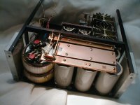
toroids are paralleled, stacked chassis left front (looking from the front). Cap bank is 6 cans paralleled filling the remaining space along the front (~17" wide). Stud mounted rectifiers on the ends of copper buss bars on top of the caps - AC runs from the toroids to 10ga. going between the rectifier tabs.
How have you arranged the supply wires. (this is for the instability with ground issue).
B+/- comes off the tabs on the ends of the buss bars (close to the toroids as it is) and to each channel via #10 wire Ground comes off the center of the ground buss to each channel's board as #16 wire and to the rear of the chassis as two runs of #10 to speaker ground.
You didn't complete a conductive loop through the toroid by mounting bracket, did you?
Heh. no.
I believe you are picking up the inductive current generated magnetic field of the toroid primary via it's feed wires, and the antiphase hums are a result of being on opposite sides of the dipole field. Single ended, your design (physical, not electrical) is incapable of dealing with this intercepted signal..
Nice thought... but it fails to explain why removing the "offending" channel from the chassis and routing the wires a different way yields the same results?? This is the channel with the "raised" hum level when the input grounds are connected.
And, the offending channel is the one farthest (other side of the chassis) from the toroids!!
I suppose I might then also remove and reroute the "good" channel and see what happens then... I may yet do this.
Your descriptions did not help...need input!!!(johnny 5)
Cheers, John
Francis: the (-) input is grounded to a "ground", tried different "grounds" the best one is as described in my post iirc. The (+) input is grounded via a shorting plug at the RCA sitting on a pigtail.
I may also try running the "bad channel's" ground from the other channel's ground, rather than back to the PS ground point, and see what that looks like, and vice-versa on that...
Quasi: the power supply can be grounded to chassis or not, for this particular issue it shows no difference.
Just getting back to this nightmare scenario today, I thought that since the soft start relays are being run off 120vac (!!) I might put some matchbook covers (no matches) in to make the contacts, no power to the coils and bring it up on variac and see if that is where the differential signal is being generated - I hope not - but we'll see... If necessary I'll dork it to DC.
And yes, the instability with the ground being moved is quite disconcerting, but not unheard of...
_-_-bear
bear said:
Pix may come, if I don't figure it out soon!
Hope so, the descriptions, while ok, don't help me..
Don't make me drive up there!! fix that camera..
the primary side of the mains, comes between the two channels through a section of BX (shield) along the bottom of the chassis from the rear panel (not installed yet). It goes to a soft start relay chassis mounted between the two channels toward the front of the chassis. The power supply is at the front of the chassis.
Ah, so run the bad stuff right down the middle of the whole shootin match..don't ya hate that??

Is BX a good magnetic shield? I'd think not...you're better off runnin the ac lines coaxially to eliminate ALL external magnetic fields..pick up a good piece of belden 88232 for your ac run. both shields are #14 awg, leave the center alone...they spec the cable at 300 vrms, should be adequate.
BTW..if you setup a dipole field loop intercept, further away don't necessarily help..and you aren't talking about lots of voltage referred to the input.
toroids are paralleled, stacked chassis left front (looking from the front). Cap bank is 6 cans paralleled filling the remaining space along the front (~17" wide). Stud mounted rectifiers on the ends of copper buss bars on top of the caps - AC runs from the toroids to 10ga. going between the rectifier tabs.
You used both cathode down and cathode up studs?
I'd have issues with the heat sinks your using for the studs, but only if you were approaching thermal limits...from your website, looks like you da king of overkill..

... but it fails to explain why removing the "offending" channel from the chassis and routing the wires a different way yields the same results?? This is the channel with the "raised" hum level when the input grounds are connected.
And, the offending channel is the one farthest (other side of the chassis) from the toroids!!
Chassis eddies are funny things..as well as dipole fields.
Try using some ferrite and wave it about the guts, see if you enhance the hum with it..it could help pinpoint the trouble spot.
Cheers, John
jneutron said:
Hope so, the descriptions, while ok, don't help me..
Don't make me drive up there!! fix that camera..
Ya, well the weather is fine and the trees are all green! C'mon up! :- )
The image if it shows up... will require some imagination as the "good" channel is not shown in place, and no wiring has been done for the PS, and only one of the two terminal blocks (the back one) is actually there... otherwise pretty much the layout...
Ah, so run the bad stuff right down the middle of the whole shootin match..don't ya hate that??
Is BX a good magnetic shield? I'd think not...you're better off runnin the ac lines coaxially to eliminate ALL external magnetic fields..pick up a good piece of belden 88232 for your ac run. both shields are #14 awg, leave the center alone...they spec the cable at 300 vrms, should be adequate.
Ya, should be fine... it's a 100% shield, in this case it is aluminum BX. And 14 ga is too thin for my taste on the mains... using 10ga. Ok, so I am crazy? Sure. Ok. Some time when I don't want to debate silly things we can talk about if you can measure or hear it...

Other stereo amps of similar circuitry, but not balanced have the same run and more of AC power down the middle without the shield (hey - get rid of the shield!!??) and not this problem.
BTW..if you setup a dipole field loop intercept, further away don't necessarily help..and you aren't talking about lots of voltage referred to the input.
You used both cathode down and cathode up studs?
Yes. Nice... no heatsinks... copper buss bars - tapped, w/1/4-24 nuts also... high contact & impossible to get hot.
Rotten thing about it is that you can hear some differential using the same modules with less power supply on creshendo w/ complex passages - no problem.I'd have issues with the heat sinks your using for the studs, but only if you were approaching thermal limits...from your website, looks like you da king of overkill..
Chassis eddies are funny things..as well as dipole fields.
Try using some ferrite and wave it about the guts, see if you enhance the hum with it..it could help pinpoint the trouble spot.
Interesting idea... increase the inductance, eh? Hmmm
Anyone else with some innertesting idees??
Cheers, John [/QUOTE]
Attachments
Elementary, my dear Watson!
I thought people would want some closure on this...
...johnnyneutron was on the right track!
Turns out the two 110vac relay coils are/were entirely responsible for the induced hum. How or why they would emit a field that is sufficient to induce the hum is somewhat surprising and unclear.
But, my dear Watson, this accounts fully for the anti-phase nature of the induced hum! Since the relays were wired with a feed wire to the coils between two relays, this places the coils out-of-phase!
Back to DC relays... heh.
(I threw the AC relays in to save time/money/effort and an extra power supply - so much for "time saving steps"!)
FYI, copper shielding added on either side of the relay chassis (see photo in earlier post) was NOT sufficient to reduce the effect! Maybe Mu metal would have?
Interestingly, the two stacked toroids have nil effect... the stupid little relays coils do!
Well, Watson, another tough case solved!
(I hope... putting in the DC relay supply now...)
_-_-bear
mu metal is seldom necessary, iron is cheap and a really good magnetic flux conductor
combined with the high magnetic reluctance of air, some light gauge iron (low carbon steel) can short out the offending magnetic flux - you would usually need the iron anyway with mu metal to divert most of the flux to avoid saturating the mu metal
sometimes a simple "U" of galvanized sheet or "tinned can" stock can divert enough flux although separate closed boxes for source and victim is used in high precision instrumentation - would a soup can fit over the relay?
Thanks for the idea... but the sucker is on an aluminum sub chassis already. If you look at the pic in my earlier post you'll see the top of the two relays sticking their tails out behind the caps...
I switched them to DC relays. No hum, no relay noise.
The existing power tranny for the LEDs (I forgot what I used...) is peachy keen fine using the outer taps to run the relays... so I am home free without a new LV supply in the box!
Lesseee... at shop rate, multiply... yeah an unaffordable soft start circuit! Heh.
But, I will keep the soft iron idea in mind for future flux battles!
tnx...
_-_-bear
Re: Elementary, my dear Watson!
Actually, you had already stated you'd be trying without energizing the relay...you didn't need my help at all..congrats..
Oh, it's "supposed" to be jimmy..I love that show..
The relay coil is a solenoid.. The field return for the solenoid is outside the coil. The magnetic circuit of the relay itself is not designed to contain the flux really, just channel enough of it to pull the contact iron down. So, typically by design, they don't try to contain the field. The toroids, on the other hand, contain the field (for the most part) entirely by design.
Actually, since you now know what the prob was, you could easily work around it if you wished..
Umm, copper in reasonable thickness will not contain mag fields at 60 hz. mu metal would be much better. Gotta have some permeability above 1..
Thank you for updating us on your trials and success..
Cheers, John
bear said:I thought people would want some closure on this...
...johnnyneutron was on the right track!
Actually, you had already stated you'd be trying without energizing the relay...you didn't need my help at all..congrats..
Oh, it's "supposed" to be jimmy..I love that show..
Turns out the two 110vac relay coils are/were entirely responsible for the induced hum. How or why they would emit a field that is sufficient to induce the hum is somewhat surprising and unclear.
The relay coil is a solenoid.. The field return for the solenoid is outside the coil. The magnetic circuit of the relay itself is not designed to contain the flux really, just channel enough of it to pull the contact iron down. So, typically by design, they don't try to contain the field. The toroids, on the other hand, contain the field (for the most part) entirely by design.
(I threw the AC relays in to save time/money/effort and an extra power supply - so much for "time saving steps"!)
FYI, copper shielding added on either side of the relay chassis (see photo in earlier post) was NOT sufficient to reduce the effect! Maybe Mu metal would have?
Actually, since you now know what the prob was, you could easily work around it if you wished..
Umm, copper in reasonable thickness will not contain mag fields at 60 hz. mu metal would be much better. Gotta have some permeability above 1..
Well, Watson, another tough case solved!
Thank you for updating us on your trials and success..
Cheers, John
Cap connections
Hi Bear
Good that you sorted the hum, but I noticed something in the pic that's a hole I fell into once myself, which can potentially cause hum and other problems.
Your filter caps are connected with big busbars. This is good. But both the infeed and the outfeed to the filter caps appear (as far as I can see from the pic) to be taken from one physical place. This is not so good, because the bulk of your reservoir caps are connected 'out on a limb' (on a branch) from the main flow of current and this reduces their effectiveness. The actual value of capacitance participating in the filtering may be significantly lower than you think.
What would be better would be to connect the leads from the rectifier + and - to the busbars at the rear (transformer side), and take the filtered power feed for the amplifier from the other side of the busbars (ie front side of the amp). This would place all caps directly along the path of current flow and maximise their effectiveness. An engine analogy would be a cross-flow head.
One can often get away with the 'caps out on a limb' at 50/60Hz, but in switchmode power systems it's a big no-no. Having said that, I built a small 50Hz PSU for a preamp once and did 'caps out on a limb' and wound up with a hum.
Even though you've sorted your hum problem (and one shouldn't fix anything that's not broke, I know!), I really would try re-wiring the cap busbar feed in the way I've described. It could make the amp sound better - a bit punchier in the bass.
Cheers
John H
John,
Interesting!
Can you point to any citations or sources on the idea of taking the load off the opposite end of the buss bars from the feed? I suspect the SMPS folks beat this one into the ground years back, but I wasn't subscribing to the industry mags during most of the SMPS upswing period and probably missed a whole lot there...
I can give that a shot and see what it does!
And actually, there is still some very low level hum/loopyness problem to deal with, but I'm closer to DFQ now, with one channel very low, the other one, not *as* low... Grrrr...
_-_-bear
Ho Bear
I can't think of anything specific in the literature, it crops up over and over again, but the theory is simple - I'll do my best to explain.
An electrolytic capacitor may be thought of as an ideal capacitance in series with a small resistance, called ESR (Equivalent Series Resistance). At 50Hz we can forget about inductance and use this simple model of a cap.
The resistance of your 'branchline' is probably only a few milli-ohms. But the effectiveness of the smoothing cap is inversely proportional to it's ESR at 100Hz, which in the case of big caps you're using is also only a few milliohms at 50Hz. The ESR is what conducts the ac ripple component of the load current to ground. The lower the ESR, the better the ac ripple is conducted to gnd. And It so happens in a practical cap that ESR goes down as capacitance increases, which is why big caps do a better job of smoothing out hum at 50Hz than little caps.
The few milli-ohms of your branchline is in series with the cap's internal ESR. So the ac ripple current flowing down the main current path sees a larger effective ESR and develops a larger voltage across it, causing hum.
Hope this helps. To test the concept, I suggest you do an quick and simple experiment by deliberately connecting your caps to the mainline on a 'branchline' via a few feet of thick wire, to exaggerate the effects. See what hum you get then!
Then try the 'feedthrough' approach by connecting the amp to the opposite side of the busbars as I've suggested.
Regards
JFH
- Status
- This old topic is closed. If you want to reopen this topic, contact a moderator using the "Report Post" button.
- Home
- Amplifiers
- Solid State
- Q: Residual Hum, Grounds, Loops & Amps