Re: Re: Not that smart .....but
Thanks Kanwar. So the negative swing of the output sinewave is added in part to the available gate drive voltage via the charging capacitor. I got it. Can you please edit my cct with indicative values in the "Another quasi-complimentary amp" thread to show me how it would fit in that? For that I would honor you forever etc....
Cheers
Workhorse said:
Hi Quasi,
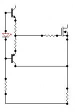
Bootstraping is used to boost the drive signal to get maximum swing. This is how it works.
in no signal conditions the cap will be charged at a refernce voltage between the resistor and output. When the lower mosfet starts conducting the the out put swings negative and then the Voltage across cap will be Vref+Vnegswing and then it gets charged to high voltage and again when positive signal appears, the the gate of mosfet sees an elevated voltage due to charge stored by cap and it gets an extra voltage at gate by the virtue of virtual supply emulated by the cap between resistor and output , thus the output swings to rail.
This technique is always used in Class-D drivers to get max High side mosfet swing.
hope you understand it.
Thanks Kanwar. So the negative swing of the output sinewave is added in part to the available gate drive voltage via the charging capacitor. I got it. Can you please edit my cct with indicative values in the "Another quasi-complimentary amp" thread to show me how it would fit in that? For that I would honor you forever etc....
Cheers
lumanauw said:Hi, Kanwar,
I think your design of full Nch+folded cascode could end up in a good DIY amp. Please keep up the good work
Thanks for the supportiveness and thanks for further encouragement.
darkfenriz said:Sorry Kanwar
I wanted to ask you:
why don't you join pnp driver's COLLECTOR with mosfet's source?
this could change voltage drop on source resistor at HF.
Suggestion noted!
Thanks for the comments
New update schematic.
Attachments
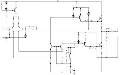
Using source resistors goes against rail to rail swings, don't you think? Of course, you have no choice if you go paralelling output devices.
I would not connect the C of the driver to the source of just the 1st MOSFET, as it worsens current sharing at switching. Not much of a problem for resistive loads, but for reactive...
I would not connect the C of the driver to the source of just the 1st MOSFET, as it worsens current sharing at switching. Not much of a problem for resistive loads, but for reactive...
darkfenriz said:Yes, that's it.
wondering if you still need gate resistor now... as slew should be fast and pretty symetric compared to other types of driving.
best regards
Hi DarkfenriZ,
In reality one must use gate resistor or Ms Oscillation would welcome unintendedly...............
Thanks for the information.....
and thanks again for your effort
What are your views regarding the new biasing regulator and push-pull drivers .....
best regards,
Kanwar
Hi darkfenriZ,
I simulated the design but, its slew rate is nod good and again it has very low open loop gain , thats why i am going to implement second differential + cascode loading in the place of folded cascodes, thereby facilitating the increase in gain and elimination of miller effect to some extent as well.
what do you think about this.
regards,
Kanwar
darkfenriz said:Hm... strange
everything seemed OK.
push-pull drivers were good idea,
bias regulator did not provide thermal stability, but it shouldn't affect slew
maybe you've overcompensated fequency?
I'll try to simulate it too and maybe change some bits and pieces.
regards
Yeah , the PP drivers were a good idea
The bias regulator has nothing to do with slew or gain.
I donot even use the compensation cap at the feedback till now.
Waiting for your sim results................
cheers,
kanwar
Hi,
I just simulated this amp with some tweaking and now the results are far better than previous ones.
Just a question ever tried to drive the mosfets with the opamps.
I just saw QSC PL9.0 uses opamps to drive the mosfets.
here is the schematic link.
http://www.qscaudio.com/support/library/schems/pl90.pdf
regards,
kanwar
Hi darkfenriZ,
Have you come up with your simulation results, just waiting for them...........
The folded cascodes are just good for less phase shift at high frequencies , but the open loop gain still suffers alot, i need to check it throughly... but very busy, but might give some precious bits of time to this DIY amp and it will be a project in reality very soon.
reply soon..... waiting
back again.......
just going to test the very much appriciated design of mine.......
input -> differentials with cascode loading....
VAS -> again differential with something extra....++
Driver stage -> DarkfenriZ Current Mirror style or Kanwar custom driver ++ pushpull effects...
Output -> all of you know that will would be our N-Channel mosfets
regards..
Kanwar
amplifierguru said:End result Kanwar, in measures we can appreciate? The ++ features are great for the marketing dept. Results count cross ref'd against a BOM and for DYI degree of difficulty?
Greg
thanks Greg I really appriciate it to the utmost depth .......
hi dark fenriz,
Your current mirror decreases the openloop bandwidth and also causes stability problems in high frequency region....
rolling back to push-pull drivers and folded cascode increases the performance and using regulated bootstraped driver supply eliminates the seperate supply issue and solved the prblem alot....
regards,
K a n w a r
- Status
- This old topic is closed. If you want to reopen this topic, contact a moderator using the "Report Post" button.
- Home
- Amplifiers
- Solid State
- NVMOS amplifier