Hi,
Can anyone please kindly provide info about these :
1. With the same x-section, how would the thermal resistance changes as a function of the length (or at least a rough estimation?) I guess that it would not be so simple as 1/2 the length, double the resistance?
2. Any recommendations for the base thickness?
3. What about the fin thickness?
4. If we were to use an angle bracket, what would be the reasonable thickness? I have been using 2.5mm -- 4.5mm
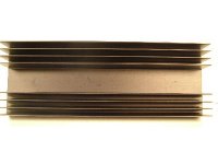
5. Assuming there are fins all over the base instead of some 'blanks ' like what's in the picture, how much better can one work with vertical fins instead of horizontal fins, assuming the fins' surface area are the same in both heatsinks.
Thanks for your input.
Can anyone please kindly provide info about these :
1. With the same x-section, how would the thermal resistance changes as a function of the length (or at least a rough estimation?) I guess that it would not be so simple as 1/2 the length, double the resistance?
2. Any recommendations for the base thickness?
3. What about the fin thickness?
4. If we were to use an angle bracket, what would be the reasonable thickness? I have been using 2.5mm -- 4.5mm
5. Assuming there are fins all over the base instead of some 'blanks ' like what's in the picture, how much better can one work with vertical fins instead of horizontal fins, assuming the fins' surface area are the same in both heatsinks.
Thanks for your input.
Attachments
Help is on the Way
Good explanation is here:
http://sound.westhost.com/heatsinks.htm
SPreadsheet for calculation is here:
http://sound.westhost.com//download.htm#hsink
Look for heatsinkzip.
Hope this helps!
Mark
Good explanation is here:
http://sound.westhost.com/heatsinks.htm
SPreadsheet for calculation is here:
http://sound.westhost.com//download.htm#hsink
Look for heatsinkzip.
Hope this helps!
Mark
Hi,
the heatsink dissipation increasing in proportion to the square root of the length. i.e.double length gives about +40% thermal capacity & 4 times length gives about double capacity.
The fin length should be about 10 times the root thickness and can taper to about 30% to 50% thickness at the tip.
for natural air cooling spacing about 8 to 10mm.
fins sideways reduce dissipation by about 20% and lying on its back reduce about 50%.
The thickness of the angle should be enough to stop it bending when bolted tight, about 6mm.
Taking a guess at base plate thickness and using the fin dimension I think the base plate radius from the heat source should be about 10 times the thickness i.e. 200mm square with one transistor in the middle would require a plate about 10mm thick.
- Status
- This old topic is closed. If you want to reopen this topic, contact a moderator using the "Report Post" button.