I think you've misunderstood what I have to work with. I've got an AVR (Onkyo TX-NR609) which gets signal from HDMI and has only speaker level outputs. My plan was to use a pair of resistors to pad down the speaker output (because there's no other output) to line level, run it into one of my MiniDSP's unused channels, do a little processing and then feed it into an external amplifier.
If the AVR had pre outs, this would be a non issue, but what I'm planning to do would mean that the center channel section of the amp in the AVR is only seeing ~2k ohm rather than the 6 ohm center channel speaker it has on it's outputs now.
Found the service manual. It seems that this model is based on the same circuits as some other models with pre-outs (such as the DTR 30.2).
On page 7 (section J4..J6), you can see pre-outs are definitely part of the design, at least for some versions.
Page 24 shows the mainboard with the RCA connectors for the analogue in- and outputs. Chances are your amp simply has the same pcb without the pre-out RCA-connectors installed. I don't know if the pcb has reference designators printed on it, but the centre channel (and subwoofer) pre-out should be connector P4011.
Perhaps creating your own pre-out is as simple as looking at the schematic to see which components need placing. Maybe the only thing that needs to be placed is an RCA-connector, and maybe a resistor and a few caps.
Attachments
Hmmm, after googling some images of your amp, I noticed P4011 must already be installed. The upper one is called "subwoofer", the lower one "pre out".
According to the user manual for this model, both are for subwoofers. I would expect J4003 to have a jumper wire installed.
Perhaps a good look inside your amp could tell more (but you'd probably have to remove the HDMI connector board). Maybe post a (high res) pic?
According to the user manual for this model, both are for subwoofers. I would expect J4003 to have a jumper wire installed.
Perhaps a good look inside your amp could tell more (but you'd probably have to remove the HDMI connector board). Maybe post a (high res) pic?
Attachments
Last edited:
Hmmm, after googling some images of your amp, I noticed P4011 must already be installed. The upper one is called "subwoofer", the lower one "pre out".
According to the user manual for this model, both are for subwoofers. I would expect J4003 to have a jumper wire installed.
Perhaps a good look inside your amp could tell more (but you'd probably have to remove the HDMI connector board). Maybe post a (high res) pic?
Yeah, I'll pop it open tomorrow and dig around. It does have 2 subwoofer pre-outs, which are summed, and a "zone 2" pre out, which stupidly only works while using analog inputs.
I have company coming over later today so I've gotta keep everything running for now, but tomorrow I'll have time to unmount it from the wall rack and pull it apart to see what the story is.
Thanks for the help!
You're welcome!
I had another look at the schematics and trace layout of your amp (designated as T6 in the manual), and I'm not entirely sure yet, but somehow it looks like it's only a matter of cutting the wire link in J4003. If J4097 and J4108 are installed, you should have centre channel on one of the two RCAs of P4011 (based on the image of a TX-NA-609 which is designated as A6 in the manual, it's the upper one).
I had another look at the schematics and trace layout of your amp (designated as T6 in the manual), and I'm not entirely sure yet, but somehow it looks like it's only a matter of cutting the wire link in J4003. If J4097 and J4108 are installed, you should have centre channel on one of the two RCAs of P4011 (based on the image of a TX-NA-609 which is designated as A6 in the manual, it's the upper one).
Attachments
Last edited:
You're welcome!
I had another look at the schematics and trace layout of your amp (designated as T6 in the manual), and I'm not entirely sure yet, but somehow it looks like it's only a matter of cutting the wire link in J4003. If J4097 and J4108 are installed, you should have centre channel on one of the two RCAs of P4011 (based on the image of a TX-NA-609 which is designated as A6 in the manual, it's the upper one).
Aha! So, probably to cut production cost, they used the same pair of RCA outs, but simply disconnected the center channel output and bridged it to the subwoofer output, creating 2 sub outputs...if it's really as easy as it looks, this can probably be done very easily. Or, I could even go all out and tap into that ribbon cable and give myself a full compliment of pre-outs.
Wonderful, I'm thrilled.

Thanks again, I'll be sure to post up a pic before I start cutting, but from the looks of that schematic, it should be nothing major.
So, I guess that means I can go into the pre out and leave nothing attached to the speaker output and the amplifier will be undisturbed doing this? Or would it be better to have some way to sever the connection to the internal amplifier when using the pre out?
It's what it looks like. The only other difference I found (for the centre channel, that is) is that R4072 is 220k in the models with centre pre-out and 22k in the models in which it is SW pre out. May work fine with 22k, though, so try this first, you can always replace it later, if needed.
If you want to go for all channels pre-out, it will be more work, but you would more or less end up with the TX-NA609 (which looks like a Japan only model). The differences are listed in the tables in the upper right of page 7. I don't think that cutting into the ribbon cable will be necessary, just mounting and/or modifying the relevant components.
Just leave the speakers disconnected, the power amp will be fine with no load (if it wouldn't, there would be a BIG warning in the user manual!), and in the USA probably also printed next to the terminals.
Last edited:
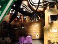
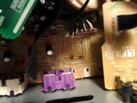
Beautiful. It works. Before and after pics!
Can't thank you enough for digging up that service manual and pointing this out. I now have 1 subwoofer pre out and 1 center channel pre out instead of redundant subwoofer outputs.
Can't thank you enough for digging up that service manual and pointing this out. I now have 1 subwoofer pre out and 1 center channel pre out instead of redundant subwoofer outputs.
Attachments
You're welcome and good to know it works!
The before and after pics are a nice touch. They confirm my suspiscion that the service manual isn't completely correct (J4097 and J4108 are neither in the schematics, nor in the tables). Luckily the pcb view did show them and the traces.
The before and after pics are a nice touch. They confirm my suspiscion that the service manual isn't completely correct (J4097 and J4108 are neither in the schematics, nor in the tables). Luckily the pcb view did show them and the traces.
- Status
- This old topic is closed. If you want to reopen this topic, contact a moderator using the "Report Post" button.
- Home
- Amplifiers
- Solid State
- Running amps unloaded