Hi all,
I've been testing for a while the amp I've build some weeks ago; and I'm very pleased with the results of it... But there are still a few questions left in my mind.
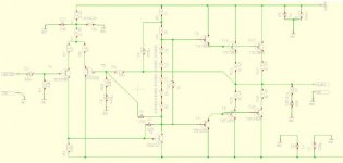
The amp produce a very low sound (maybe because of the HUGE PSU); I thought I could help this by pulling up the higher and the medium frequencies by bypassing the bias diodes with a cap; but this had no effect on the sound.
So what value do you recommend for this cap?? Are there any other solutions? (schematic below)
I'm also building a pcb layout for my further amps, how thick should the tracks be? Are there any guidelines for this ?
(i.e. ?? ampère => ?? mm thick)
thank you all,
HB.
I've been testing for a while the amp I've build some weeks ago; and I'm very pleased with the results of it... But there are still a few questions left in my mind.
The amp produce a very low sound (maybe because of the HUGE PSU); I thought I could help this by pulling up the higher and the medium frequencies by bypassing the bias diodes with a cap; but this had no effect on the sound.
So what value do you recommend for this cap?? Are there any other solutions? (schematic below)
I'm also building a pcb layout for my further amps, how thick should the tracks be? Are there any guidelines for this ?
(i.e. ?? ampère => ?? mm thick)
thank you all,
HB.
Attachments
low sound
When you mention "low sound" i think you mean the absence of high frequencies.
You can try to decrease the value of C4 (220 nF) ,because this one seems to be responsible for the negative feedback on high frequencies.
But be careful.... if it's too low it may cause oscillations!
regards
Arne
")
When you mention "low sound" i think you mean the absence of high frequencies.
You can try to decrease the value of C4 (220 nF) ,because this one seems to be responsible for the negative feedback on high frequencies.
But be careful.... if it's too low it may cause oscillations!
regards
Arne
Yes, that's what I mean with the low sound; the sound is good when I turn (on my mixers equaliser) the low freq. to about a quarter of the range (of that potm.), the mid freq. turned to normal (= centre) and the higher freq. at full range.
If there's one thing left what I don't understand about the schematic, it's the function of C4; it's still in the design because this is in fact a modified amp (the design failed when I build it for the first time). I often don't see this cap in other designs, can I leave it away?? Because I left it away in the schematic for which I'm designing the pcb.
thanks,
HB.
practical questions
Hugo,
Still, 220pF is rather high, I would try 100pF or lower.
Another thing I noted is the cap from the bottom of the bias diode string to the base of T5 I think it is. How large is that one? It does roll of the closed loop gain with frequency and could cause the effect you describe, but I can't read the value so don't know if it is significant.
Jan Didden
practical questions
Hugo, no,
I mean the cap from the bottom of the diode string to the base of the right-hand transistor of the input LTP. Because the bottom of the diode string is for AC (almost) identical to the output voltage, this cap is effectively in parallel with the (10k?) feedback resistor, and therfore rolls off the closed loop gain with rising frequency.
Jan Didden
practical questions
Ok, now I get it.
The 220pF with the 10k gives a 3dB point of the closed loop gain of something like 65kHz (f=1/(2.pie.R.C)) so that cannot be the problem.
220pF is high here though, normally you see here small values up to 50pF to correct the phase shift, but if it works with 220pF it's OK.
What's the Ccb on that Vas stage below the diode string?
Jan Didden
what do you mean with Ccb? I guess the cap between the collector and the base of T6 => 100pF.
Other cap values:
bootstrap-capacitor: 220 µF
cap parallel over the bias diode string: 1µF
cap below R10 = 470µF
input cap = 10µF (in combination with 10K resistor), maybe I can solve the problem with lowering this cap, but this wouldn't solve the main problem.
(sorry for the unclear picture)
thanks,
HB.
Hugo, a few more tips for your consideration:
Put a 470pF polystyrene cap from T4 base to 0V (for stability)
Replace R1 R2 C11 D6 with a CCS (for better CMRR)
Increase C12 to 100uF (to reduce impedance of the diode chain)
Add bias resistors between T8 emitter and T11/T12 emitters. Repeat for the neg half. Use 100 ohms. (for linearity)
Remove C9 and replace R5 and R6 with a CCS. (for linearity)
Remove C4 altogether - but make sure the amp is stable. (for linearity)
BAM
BAM,
you've just described what my new design looks like.
I didn't like bootstrapping at all; so the solution was to add a current source instead of the two resistors.
I've increased the cap C12 to 100µF, but there was no difference in sound...
Can you explane the thing about the 'bias resistors'?? I've also read about a resistor between the emittor of T8 and the emittor of T7 (and a cap placed in parallel). It's said to improve the sound, but I've never read why.
thanks,
HB.
The idea is to run the drivers in a reasonably linear region most of the time...to reduce distortion. It will be less important if the output devices are run at high standing current, but bear in mind that unless the betas of the output devices are the same then the drivers will be biased differently from one another at 0V output.
Using resistors between driver emitters and output emitters is one way. Another is to run a single resistor between driver emitters. The effects on distortion depend on the deviced you are using and how you match your output devices and drivers. Measure the distortion in each case if you have the equipment.
In any case I would not introduce a capacitor across the bias resistor. This is because the Vbe of the two drivers will not always be required to be the same - because the output devices are non-linear. If you use a capacitor to force the voltage to be the same then the drivers will be pumping non-linear current to charge the cap up and down with a non-linear voltage. The impact is frequency-dependent too. I suppose if the output devices are not matched well then it might make a bad job better, but normally I wouldn't do it.
Tip: think hard about the effects of capacitance in non-linear circuits. Where in the circuit is it ok and where not?
BAM
- Status
- This old topic is closed. If you want to reopen this topic, contact a moderator using the "Report Post" button.
- Home
- Amplifiers
- Solid State
- a few practical questions...