hi everybody..
does someone know how to make a correct dimensioning of the heatsink for an AB class amplifier?
now i'm trying to solve this problem..my AB has +-30v supply and 4ohm load(push pull,so 7,5Amax),uses a tip35 and a tip36;the maximum power dissipation, in my opinion is when i have 15v out, so about 50w..put it's a peak power and every bjt is conducting just for half period..
so does anybody know how to calculate the effective power dissipation to obtain a correct heatsink?(i don't want to buy tons of alloy and fans...)
thanx a lot..
As a general rule, 2 x 60W Class AB amp modules will require around 0.4C/watt of heatsink.
This means that 100W of dissipation - 50W per channel, about right for the max into 4R loads with 36V rails - will heat the sink 40C above ambient. If ambient is 25C, then this is 65C - and you don't want to go any higher.
Incidentally, maximum heat dissipation occurs at around 60% output power and is much higher with 4R loads than 8R loads. The example quoted above is worst case, and it is important to note that there will always be a situation which is actually worse than worse case. A good example would be full volume heavy metal, open air venue in 100F heat with the amp in direct sunlight. Don't laugh - it happens!
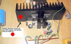
If you use forced air cooling, you can reduce the heatsink rating by approximately three times. But you'd better be sure the fan is reliable.......
Cheers,
Hugh
This means that 100W of dissipation - 50W per channel, about right for the max into 4R loads with 36V rails - will heat the sink 40C above ambient. If ambient is 25C, then this is 65C - and you don't want to go any higher.
Incidentally, maximum heat dissipation occurs at around 60% output power and is much higher with 4R loads than 8R loads. The example quoted above is worst case, and it is important to note that there will always be a situation which is actually worse than worse case. A good example would be full volume heavy metal, open air venue in 100F heat with the amp in direct sunlight. Don't laugh - it happens!
If you use forced air cooling, you can reduce the heatsink rating by approximately three times. But you'd better be sure the fan is reliable.......
Cheers,
Hugh
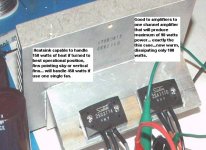
90 squared inches of aluminium, 10 fins measuring..
something alike 3 by 3 inches each one...or any other distribuition or shape, since you have around 9 squared inches of aluminium surface in contact with air (considering only one side) will be enougth to dissipate 100 watts of heat, and this corresponds to a single 50 watts amplifier channel working near the clipping.
In the reality, the area that will loose heat to air will be doubled in reality, as each fin has at least two big flat sides, and, both sides will work.
So you can re-arrange this basic calculation...you can say that 18 square inches of aluminium in contact with air will be enougth to dissipate 10 watts.
Those watts are not the audio power produced, as this can be half the entire power producing heat.... 65 percent normally produces audio, but for safety reasons...better to think in fifty to fifty....half power to speakers and half the power lost entirelly as heat, producing no work...so, 50 watts amplifier will produce 100 watts of heat...if stereo, 50+50 watts amplifier will produce 200 watts of heat.
For calculation, I do not use both sides.some psychological defense against enormous area numbers...i take into account only the area of one side....this way, 3 by 3 inches thin will dissipate around 10 watts of heat.... 9 square inches in contact with air to dissipate 10 watts (if you prefer, 18 square inches in contact with air to dissipate 10 watts).
This will be able to hold 100 watts of continuous power, and may be the maximum undistorted steady sinusoidal undistorted tone you will reproduce over 4 ohms loads.
Atention!...this is for a single channel, double to a stereo amplifier... in this case use around 20 fins, having something around 180 squared inches.
This is a 45 years pratical use, giving good results to 30 degrées centigrades environment.
Heatsink must be outside the enclosure, mounted in position to have free air circulation...better in the back panel, as you can keep it projecting outside the table.... heatsinks in excess of length related the table bottom extreme, to allow a good convection air movement, were air flow to the ceiling sucking new fresh air from the floor...hot air goes high, cold air goes down, just to remember.
If you install inside cabinet, use fan and reduce the size 3 times as hugh told, but for safety reasons use 2 fans.... if one stop, you will have some guarantee not to burn transistors.
Reduce fan speed using LM7808 DC regulators chips, TO-220 capsule as you know...maybe 1 square inch heatsink will be needed to this chip... remember that input voltage to those chips cannot be over 25 volts.
Side heatsinks are wonderfull, but produce wires to the left and the rigth... making assemble worst than one single cable.
The second problem is that the heatsinks will be over some table...and distance is needed to air flow.... at least one inch free...and this is very bad related to heatsink capacity,...in this case increase 30 percent your heatsink area to be more safe.
As you use to see advises in Television brochures, or operational manual, they use to ask you to keep at least 3 inches of free air around television set, also space behing and space related side panels, beeing the more important the upper space.
All that care to allow convection air cooling..you will see under television sets that plastic are full of holes, more than 25 percent of the entire area is opened to capture air...and this was made for safety reasons.
Well, my English is awfull, but heatsink will work very good.
regards,
Carlos
Considering the dissipation power, even to class A, where continuous power need to be
dissipated, you can use this simple method...but to continuous power, better to multiply the result to three....as AB consumption is always changing, and most of time will be under the average dissipation.
Continuous 100 Watts is a big problem to dissipate, and enormous monsters must be used.
When you have transistor case overheating related the heatsink....this is showing that heat transference is not OK!....or problems related unflat surface, resulting bad mechanical contact related transistors and heatsink...too much bad insulator, or using transistor that cannot dissipate the power it is handling...this way, it will be a death comdemned.... a matter of time to blow. Transistor metal case, in the case of to-3 will show you if transference is OK...temperature must be almost the same heatsink temperature....for to-220, touch the metal surface and compare with heatsink...the others...plastic insulated...hehe...have to touch under the heatsink, where it is mounted, and when you perceive too much hot, that point, related the resting heatsink surface....your transistor is near to dead...Those transistors, some plastic cover, when touched over plastic must be warm, not more than human fever... feeling that it is too hot...put a fan over them, yeah!, direct over them, as junction will be near to melt when plastic case, those ones only covered with plastic case (not the ones made all sides with some plastic compound), having metal under..... when plastic case is hot...problem!
Find a guaranteed flat surface...glass or even something guaranteed flat, to check if transistor has flat metal surface...surprise!!!.... many of them are not, and need to be sanded hard with fin3 grain waterproof sand paper (500).
The transistor must receive more grease compound that it really needs, also both sides of insulators (if you use it), also the heatsink surface where it will be mounted....put it with precision, cannot skid the transistor as create some bubles of air under. The excess of grease compound can be removed using Cotton snubs.
When screwing, do not go with strengh when having two screws...first one without torsion power.... and jump to the other, and return again putting more torsion power over it.
Yes, sanding transistor will remove Chromiun finishment, and you will see how unflat transistor can be, and as annoyng result, will produce some oxide, and this is not good to heat transfer...so, carefull with grease, as it will insulate that unprotected copper surface from air, and this insulation related air will avoid too much oxide.
Heatsink fins can be very thin, and this is very good, as heat transfer is made by surface... some thick aluminium material can be good to hold some accidents without too much damage, and also, will have some delay to start to produce heat over the aluminium surface...will have some thermicall "inertia" related to start work transfering heat to surround environment.
This is made not only to use less aluminium, but also to increase efficiency with same length heatsink, as you will have more fins to work, but, beeing mechanically week, people use to put it inside amplifiers....and this turn them even less efficient than strong ones.
If you can, use the multiple thin fins units, and protect their surround with some metal bar, and this metal bar can be a good handle too.
Well, despite simple, heatsinks have a lot of tricks, and if i go on, will write many pages, and those informs are the more needed ones.
This was produced burning fingers and shorting transistors along 45 year constructing amplifiers for fun,of couse it is not precise, but may have some "room" to keep things running, as hundreds units are working till today.
regards,
Carlos
Attachments
> dimensioning of the heatsink for an AB class amplifier?
The most sensible way to arrive at an answer, for DIY work, is to study (even steal-from) a commercial amplifier of similar power rating.
> ..my AB has +-30v supply and 4ohm load(push pull,so 7,5Amax),
At a glance: +/-30VDC is 60VDC, a perfect amp would give 60V peak-peak, 60Vpp/2.828 is 21V, 21V^2/8Ω is 112 Watts audio sinewave output power.
> uses a tip35 and a tip36;
Irrelevant (unless your devices are VERY lossy).
> the maximum power dissipation, in my opinion is when i have 15v out, so about 50w..put it's a peak power and every bjt is conducting just for half period..
Ah, you will go crazy trying to plot the instantaneous dissipation. For large devices and signals above 20Hz, it is quite valid to estimate the average dissipation.
That perfect +/-60V 4Ω 112 Watt amplifier will run 78% efficiency. If the input is 100%, and the output is 78%, the dissipation is 12% of the input power. We don't yet know the input power. We do know the output power. 12%/78% says the dissipation is 28% of the output power. Heatsink must support 32 Watts.
That's all unrealistic. If you have +/-30V no-load, you may have +/-26V at full load. And you have 1V-4V of dead loss in transistors and bias. So your peak-peak is probably about 48V, your RMS about 17V, your output power about 72 Watts in 4Ω. The dead-loss drop is added inefficiency, and a real amp has idle and driver current in addition to a perfect amp's consumption. Waving my arms a bit, the observed dissipation of a Class-AB amp is never less than 40%, and often 50%, of power delivered to load at the edge of clipping. That says you heat-sink this amp for 28 Watts to 36 Watts.
The other question is: how hot? 50 deg C is a traditional value for Class-AB amps on speech/music signal. Modern Silicon will run MUCH hotter, but the loud-soft Boom-da-Boom thermal cycling can crack seals in a few hundred hard hours.
36 Watts at 50 deg C is 1.4 deg C per Watt. (Per channel! Half of that if two amps share one heatsink!)
Note that commercial heatsinks are sometimes tested at VERY high temperatures, and the degC/Watt "constant" isn't quite constant. I would use a commercial rating of 1 degC/Watt.
The simplest DIY heatsink is a flat plate. Flat plate approaches 100 degC/Watt per square inch (sorry, I don't think metric). So for 1 degC/Watt you need 100 square inches. If you mount it in the open, you can use both sides: 7"x7" will do the job.
Heat does not travel well through metal. If you put two 1" transistors in the center of a thin 7" plate, the center will run hot and the edges run only warm, barely helping. As a rule of thumb, the thickness should be about 1/10th of the distance the heat has to flow. Here the heat must flow 3 to 5 inches, average about 4 inches, so you want 3/8" aluminum plate! A more economic design uses a little more area of thinner plate: say 8"x8"x0.125".
Since an 8" vertical sink is an awkward shape, you want to use fins. If you make your own sink, don't put the fins any closer than 0.375" or the air between will stagnate. (A powerful blower can scrub much tighter fins, but is usually undesirable in home hifi.) And the thickness of each fin must be enough to carry heat along its length. The fins connect to the devices with a flat plate which also has to be very thick.
If you buy commercially designed sinks: be sure they have enough space between fins (are not designed for fan-blow operation) and have about 100 square inches of exposed surface. Get two for stereo.
- Status
- This old topic is closed. If you want to reopen this topic, contact a moderator using the "Report Post" button.
- Home
- Amplifiers
- Solid State
- ab class heatsink dimensioning