Does any one of you remember this amplifier? I happened to come across this when I am tidying up my machine. I remember that the output was something like irfp6??. His site is gone and I'm just wondering if any of you happened to have a copy of the material (he also have some wall horn material and others stuff). Or anybody knows whereabout is his site now?
")
It is a fully symmetrical differential amplifier
using JFETS cascoded by bipolar in input and VAS.
And push-pull HEXFETS IRF610/9610 in output.
Uses two resistors to reduce total gain/feedback.
R24 and R25, both 50k in VAS.
Voltage supply is high for a headphone amp +-58 Volt.
So, all the active transistors are JFET/HEXFET.
using JFETS cascoded by bipolar in input and VAS.
And push-pull HEXFETS IRF610/9610 in output.
Uses two resistors to reduce total gain/feedback.
R24 and R25, both 50k in VAS.
Voltage supply is high for a headphone amp +-58 Volt.
So, all the active transistors are JFET/HEXFET.
lineup said:Uses two resistors to reduce total gain/feedback.
R24 and R25, both 50k in VAS.
Voltage supply is high for a headphone amp +-58 Volt.
So, all the active transistors are JFET/HEXFET. [/B]
Silicon chip's Ultra Low Distortion amp uses similar to r24 r25,
excep they are 2 * 10k
allan
jmateus
I only described what i did see
in the schematic attached by FYC in this post above
http://www.diyaudio.com/forums/showthread.php?postid=807700#post807700
I know it is supposed to be a headphone amplifier
because some info I found when trying to search with google
Here is schematic FYC attached:

Herbert Fu is from Hong Kong
He has contributed a 'Son of Zen' in passdiy gallery:
http://www.passdiy.com/gallery/soz-p5.htm
He has had a geocities website, but nothing is saved from it
but a menu frame from 2003-2004, in wayback machine:
http://web.archive.org/web/*/www.geocities.com/fuherb/
His email has been, see wayback machine contact:
fuherb_at_yahoo.com
I only described what i did see
in the schematic attached by FYC in this post above
http://www.diyaudio.com/forums/showthread.php?postid=807700#post807700
I know it is supposed to be a headphone amplifier
because some info I found when trying to search with google
Here is schematic FYC attached:
Herbert Fu is from Hong Kong
He has contributed a 'Son of Zen' in passdiy gallery:
http://www.passdiy.com/gallery/soz-p5.htm
He has had a geocities website, but nothing is saved from it
but a menu frame from 2003-2004, in wayback machine:
http://web.archive.org/web/*/www.geocities.com/fuherb/
These pages are about me, a Chinese man living in Hong Kong. I publish these pages for myself, and for anyone who happens to come across and read them. It is my world in the virtual arena, a place where I can give myself a total reflection.
Herbert Fu
His email has been, see wayback machine contact:
fuherb_at_yahoo.com
Now I have managed to find
Herebert Fu full description of Lawyer amplifier,
It is at this link in wayback machine:
http://web.archive.org/web/20021008143809/www.geocities.com/fuherb/lawyer.htm
I have downloaded and save his article.
I attach the image of Lawyer!
Herebert Fu full description of Lawyer amplifier,
It is at this link in wayback machine:
http://web.archive.org/web/20021008143809/www.geocities.com/fuherb/lawyer.htm
I have downloaded and save his article.
I attach the image of Lawyer!
Attachments
Thanks Lineup for your effort.
Unfortunately nothing is mentioned on these pages about the
Lawyer amplifier except the schematic on that link.
The schematic helps a lot if one is to build the amplifier, he has
to design his own layout.
But one thing that surprises me is you mentioned that this is a headphone amplifier, it does seem the supply voltage is a bit too high for this type of amp, don't you think?
Any way it is a different design and probabaly a good one too,
a good field to experiment and investigate.
Thanks again
nothing ?????
It is a long article about lawyer
I remembered wrong, he call it 'phono amplifier'
Schematic we have is the line stage.
http://web.archive.org/web/20021008143809/www.geocities.com/fuherb/lawyer.htm
Yes, is high voltage.
A good preamplifier line stage, using this amplifier,
could have like +-24 Vdc, instead of +-58 Vdc.
It is nothing bad to have high voltage, this gives headroom for transistors
and they can operate sometimes more linear.
But a drawback is they will get closer to power limits ( with heat ).
And if you have to use those with higher current/power rating,
then you will often lose speed and linearity, that true small signal transistors have.
Another thing with higher voltage, you have to consider resistors power rating, sometimes use several metalfilm in series,
and capacitors have to be bigger (voltage).
This makes it more expensive to build with higher voltage.
Hi Lineup
Wow, such much information in such a short time.
Yes, there is nothing in Mr.Fu's web pages, actually they are
not working.
Now, the link you sent me,yes, there is a lot of information even
though the schematic and others (I don't know what they are)
don't show up at all.
Of course I was only interested in the power amplifier so all
that info about the preamp doesn't apply to me.
But whatever details I could read will be useful, apparently his
amplifier was a gem.
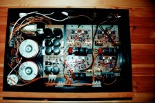
Hi, the situation is like this. I am the one who made this amp. I was very busy during the last few years and failed to maintain the website so geocities removed all my files.
The amp is a phono amp (MM, but I think it works for MC also by adjusting the gain)
The circuit is a unit line amp, and I inserted a RIAA network between 2 line amps to form a phono amp.
More circuit here which include the power supply, the RIAA network
1 channel of the amp failed a few months ago after working for several years and I have not repaired it. I think it works fine as a phono amp. Sound is clean and with lots of details.
Attachments
- Status
- This old topic is closed. If you want to reopen this topic, contact a moderator using the "Report Post" button.
- Home
- Amplifiers
- Solid State
- The Lawyer amplifier by Herbert Fu