A many designs one sees input impedance (Zi) set at 10-12k ohms by parrallel resistor. The same value is used for the NFB resistor. However, in other cases boot-strapping is used to reduce the value of those resistors and the associated noise. Boot-strapping allows a almost arbitrarily high Zi or it allows (with in the costraints of available values) a large range of impedance that could be chosen as the designer desires.
Given that most (nearly all ?) preamps one may encounter seem to be able to drive a 10-12k ohm Zi, is there any advantage or disadvantage either to making it very, very high such as hundreds of K-ohms or some specific value analogous to the 47k standard established for MM phono cartidges?
I've clearly read the 10-12k ohm figure for preamps and I've one personal experience with what happens when it is set too low, but I've not seen any further discussion regarding if there is some ideal range the value should lie within.
The NFB resistor is normally chosen the same as the input to ground to present an equal resistance to input bias currents, and thus reduce offset voltage.
Bootstraping in audio is not so much used to increase input impedance (although that is the result) as to decrease input capacitance. Normally very high input impedances would be used only with sources that work best into such loads. Tipically, however, as far as interconnecting parts on the level of black boxes, about the only use for a bootstrap would be when an input is supposed to be driven by a high impedance source, such as some tube (pre)amps.
As far as I know, line level inputs are generally specified at either 100 or 47k input impedance (although the resistance is the most part of the impedance in this case) while in power amplifier inputs, there really isn't any rigid standardisation. People tend to use between 10 and 47k, but both higher and lower have been used.
Sam9,
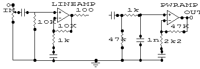
To illustrate the issue I've included a typical block schematic for a typical capacitor coupled scenario. Because there are feedback coupling C's to ground both loops derive their bias from the uotput for their -input while their + inputs source theirs through the input resistors. For DC bias equality these are made roughly equal.
Note as well the 1K and 1nF input filter, setting -3dB at 160KHz. This is common to filter RF pickup and above audio band hash from getting into the power amplifier. It's effect is less than 0.1dB down at 20KHz. However, it's values can be crucial!!!
Once I was consulting to a well known company in the US whose 'chief' engineer had 'designed' his first product - a re-hash of someone else's competent earlier design. It was horrendously hummy - so much so that part of the production and specification final inspection regime was to rotate the two internal toroidal power transformes to obtain some hum cancellation. But it simply wasn't good enough for the Japan agents who used high efficiency speakers and weren't happy. He had no solution despite repeated meetings triggered by the agents repeatedly faxing graphs of the resuduals and they weren't going away! I had a quick look at the schematic and it was glaringly obvious. That input RC filter had been set at 4K7 and 220pF! This raised the input impedance at the first transistor to 4K7 and it was susceptible to hum pickup even when connected to a low output impedance preamp. I had the production engineer change one to 1K, 1nF and test it. Their residual hum immediately dropped by 14 dB!!! He was happy he didn't need to swivel transformers in production, the Japan agents were happy. The 'designer' was gobsmacked.
Attachments
Hmmm (no pun intended) that aspect had not ocurred to if only because I've always used a much lower (120R-200R) value on the input RC. Athough that wasn't my motive, it keeps it an order or two of magnitude below the the other elements contributing to input impedance.
The whole question arose for me when trying to drive an amp with a PC soundcard. The soundcard was very unhappy until the impedance was ~30k ohm. I didn't feel like slapping a 30K resistor into the nfb just to make a soundcard happy.
Actually I don't feel like modding the amp at all, so the most probable solution will be a unity gain buffer running off a battery.
Sam9,
My amplifiers invariably use JFET front ends so 47K is no trouble and I standardise on it. My soundblaster live drives it fine.
With the RC input filter, you need to be careful that the C is not too large if your source impedance is large or unknown like off a pot! That could really roll off the high frequencies. With 1nF even a 10K pot will be around -1dB at 20KHz at centre.
amplifierguru said:
With the RC input filter, you need to be careful that the C is not too large if your source impedance is large or unknown like off a pot! That could really roll off the high frequencies. With 1nF even a 10K pot will be around -1dB at 20KHz at centre.
The output resistance of a 10K pot at the center point is 2k5 Ohms. The 1nF capacitor has ~ 3k3 Ohms of impedance at 50KHz ,so the roll off at 20 KHz , will be much greater than -6 dB.
")
Tube Dude,
Yes the centre of a 10K pot =2.5K to ground with one end earthed and the other at the low Zout of a preamp. This 2.5K forms a pole at 63.6KHz (i.e -3dB) with 1nF and the amp input is off the 1nF so it receives MORE at 20KHz (i.e. a low pass filter).
In fact at 20KHz, Vin/V = 20log (Zof1nF/Ztotal)
put simply, at 63.3KHz Zc =Zr =2K5
at 20KHz Zc = 63.3x2K5/20 = 7K9
or just considering the ratio of frequencies 63.3/20 = 3.18
so Vin/V at 20KHz = 20log(3.18/sqrt(1x1 +3.18x3.18))
= 20log(3.18/3.33)
=- 0.4 dB
Even if including the 1K in my illustration, the pole of 1nF and 3K5 is 45KHz and response is -0.775 dB at 20KHz.
Hope that helps. Your calculator may need new batteries.
amplifierguru said:
Hope that helps. Your calculator may need new batteries.
No...I think is my brains , that need new batteries....
I have wrongly made the calculation for a high pass filter , what obviously is not the case.
- Status
- This old topic is closed. If you want to reopen this topic, contact a moderator using the "Report Post" button.
- Home
- Amplifiers
- Solid State
- Amp input impedance question ?