Hello,
The idea is very old. I found it in my older notebook (not computer). original file was drawn by OrCAD V3.11. It isn't finish. I am used switchCad to re-draw it.
( http://home.kimo.com.tw/skychutw/Xfeed/Xfeed.htm )
Do you have any comments ?
The Xfeed circuit is also use negative feedback circuit and feedforward circuit to cancel the distortion. In a bridge balance circuit, The first amplifier have a negative feedback circuit for feeding back outputs of the first amplifier to the input of the first amplifier and second amplifier also input the differential singnal and amplified as a feedforward circuit to cancel the distortion. From the second amplifier to view, the feedback circuit and first amplifier also provide the feedforward circuit to cancel the distorion.
Regards,
Sky Chu
Attachments
This is an interesting circuit and one which, if I am not mistaken, employs the same principle as Nelson Pass's Super Symmetry patent. Clearly the implementation is different but I think it operates in much the same way. Perhaps Nelson would care to comment? You say the idea is old: do you know from where it originates?
Ian.
Ian.
Nice work, Sky!
Several observations:
Your circuit requires a balanced input with both polarities
driven.
The second schematic representing the SS circuit is not to
be taken seriously, as it was intended to illustrate the
potential for op amp use given the existence of current
feedback op amps where the + input is the low impedance
input. These do not exist in the real world as far as I know.
Having played around with the concept for about 24 years,
I can say that you are not going to get significant benefit
from implementing the circuit with high open loop circuits for
a couple of reasons.
The stability problems with high open loop circuits are
excessive, and I spent a couple of years trying to make
a power amp with circuits that looked a lot like yours,
but without satisfactory result. The circuit has a certain
"hall of mirrors" quality to it, and you can easily find each
half correcting for the correction of the other half ad inifinitum,
the result being noise and distortion due to the finite transit
times.
Only when I simplified it down to a single differential pair
(instead of two) did I get what I was looking for, and that
is at the heart of the patent.
The SS circuit works extremely well with simple gain stages
and less than 20 dB of feedback, and done properly we can
get two matched and balanced single ended circuits to have
as much as 40 dB less distortion with 20 dB of feedback.
Each output looks like its open loop characteristic, which is
not spectacular, but differentially they are excellent.
Love these new icons.
Thanks Mr. Pass !
You are master ! Yes, It is unstable and I can't solve , although it is second verison. the first verison is very unstable.
I were only tested it with breadboard and couldn't use it in power-amp. I will read your patent again !
Other, I can't find any information of Sansui's X-balance. What's patent nr ? or where ?
Regards,
Sky Chu
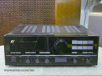
I don't know the patent nr. But I ever seen that circuit [1st circuit/Xfeed] at my old magazine as X-Balance from Sansui. [if I found that mag I will scan and post here]
And this I attached pic from http://www.retroaudio.ru/ ... Sansui model AU-a707I (1987) that have the X-Balance circuit inside ...
regards:
ragil.hastomo
And this I attached pic from http://www.retroaudio.ru/ ... Sansui model AU-a707I (1987) that have the X-Balance circuit inside ...
regards:
ragil.hastomo
Attachments
- Status
- This old topic is closed. If you want to reopen this topic, contact a moderator using the "Report Post" button.
- Home
- Amplifiers
- Solid State
- Xfeed circuit