Well here is another project I finally finished, I am on a roll 4 Projects completed over the last 4 weeks! Not completed in 4 weeks, more like 16 months. ")
This latest project is built on a pair of Kits out of Taiwan that actually sound pretty good, all things considered. The kits were $150 CAD each for PCB and all parts to mount to it. I replaced some parts with some slight upgrades, but al in all they were built as supplied. I built up the power supply with 4 x 69,000 uF caps a Fast Bridge from BigParsnip and a 1KVA 2x40VAC Plitron Toroid I had kicking around.
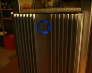
The chassis is made from rescued Car Amp Heatr sinks and some aluminum from my favourite jobber, Metal Supermarket. I have yet to put it through it's paces as a stereo configuration, but I did have one channel already running a Centre Channel in my Home Theatre. It has some real Bass Slam and Midrange Detail, great for Dialogue. It is a little harsh in the upper registers, I will probably use it as a Sub Amp for my DPL12's
Here is a link to some Photo's, feedback is always welcom as well as questions.
http://www.briangt.com/gallery/view_album.php?page=1
This latest project is built on a pair of Kits out of Taiwan that actually sound pretty good, all things considered. The kits were $150 CAD each for PCB and all parts to mount to it. I replaced some parts with some slight upgrades, but al in all they were built as supplied. I built up the power supply with 4 x 69,000 uF caps a Fast Bridge from BigParsnip and a 1KVA 2x40VAC Plitron Toroid I had kicking around.
The chassis is made from rescued Car Amp Heatr sinks and some aluminum from my favourite jobber, Metal Supermarket. I have yet to put it through it's paces as a stereo configuration, but I did have one channel already running a Centre Channel in my Home Theatre. It has some real Bass Slam and Midrange Detail, great for Dialogue. It is a little harsh in the upper registers, I will probably use it as a Sub Amp for my DPL12's
Here is a link to some Photo's, feedback is always welcom as well as questions.
http://www.briangt.com/gallery/view_album.php?page=1
Attachments
jacco vermeulen said:4 weeks !!! Are you trying to get me depressed ?
Mmm, which Hitachi 2SJ/2SK , Monsieur Energique ?
I just paid 4.5 CAD per pound for a 60 pound 10 mm aluminium plate for my Extended Leach amplifiers.
Me thinks i need to hit the car amplifier sinks too.
Hey Jacco, that would be the 2SJ162 & 2SK1058.
Here is the link again, the one I posted in the initial message just does not seem to work all the time.
http://www.briangt.com/gallery/album01
Regards
Anthony
Antonio,
had the link worked, i could have spotted the mosfet types myself.
That is an un-usual way of mounting power devices, never seen it done like that.
It must be nice hodging next to the Dubilier depot ?
A very original and economical way of building an Aleph variety.
Care to convey how to get the corners on the aluminium bottom plate so smooth ?
Did you swap to GB flag, i thought you carried the Maple leaf ?
jacco vermeulen said:Antonio,
had the link worked, i could have spotted the mosfet types myself.
That is an un-usual way of mounting power devices, never seen it done like that.
It must be nice hodging next to the Dubilier depot ?
A very original and economical way of building an Aleph variety.
Care to convey how to get the corners on the aluminium bottom plate so smooth ?
Did you swap to GB flag, i thought you carried the Maple leaf ?
Well I hate to gloat, but I got about 20 or so of those caps plus some 100 VDC versions for a pair of Anthony Holtons AV800's.
As far as the circuit goes, it is very similar to an Aelph but biased into A/B operation. I can increase the Bias to about 2 amps, normally set at 100 Milliamps, which would definately push it into Class A I suppose. I posted the scematic some time back for discussion but never got any feedback on the circuit. I should post it again here.
Round Corners, well you need a CNC milll or a coordinated XY drive on a standard mill or an Index table. If you look at the front Heatsink you can see where I was practising with an index table. In the old days a metal saw and file would have to suffice. Yes I admit having a Machine shop and being a trained machinist could have some bearing on the quality of my metalwork.
BTW Jacco I also graduated College as an Electronics Technician, went back for Digital Design, and again for Military Production training.
Regards
Anthony
PS. We never leave school, life is about learning, adapting and evolving, everything else inconsequential.
Coulomb said:Yes I admit having a Machine shop and being a trained machinist could have some bearing on the quality of my metalwork
I figured as much from the 2 stray center points on top of the square bar.
My dad had a thing with center points, i grew up in a machine shop, got my machinist training from the Dutch navy.
PS : Personally, i am training as a Leech currently.
My tutor, Mr Marshall, doesnt see much progress, but i am sucking diy-audio dry.
Nice work, Anthony.
Thanks Jacco,
BTW the GB Flag represents my Nationality, I am not yet a Canadian Citizen, even after 30 years here.
AR2 I will try to track down the supplier for you. In answer to your question I have not yet completed the Holton Amps.
I said earlier the Bias Current was adjustable, I meant the idle current is adjustable and the DC offset which is at 3mV on the right channel and 0.01 mV on the left channel. The acceptable limit according to the broken English instructions is 500mV, I guess it is within tolerance.
Regards
Anthony
Hello Jacko, now I see what you were referring to when you mentioned off centre holes. The hole centre's were determined by the top cover irrespective of where they would end up on the posts. I guess you can not see that the holes for the top cover are symmetrical.
Regards
Anthony
Regards
Anthony
Thank you Colomb for the quick reply.
Out of all searching on the web you captured two best sources for the higher powered Class A/AB amp. There are many designs for Class A up to 100 - 150 W or for amps that are 60W. It seems like choices are ether now-days digital amps or bridged configuration to reach 400 - 800 W. When we speak about this power many people react with "Do you really need that amount of power?" but if you have low sensitivity low impedance speakers that amount of power get used easily. I do not know what is yours intended use for these amps, but I am assuming for bass drivers in active config. in the decent room size. I have a same need for amp with decent current capability for sealed bass driver.
Great work on your amps, they really do look awesome.
still4given said:May I ask what process you used to do the lettering on the exterior? Looks very nice!
Thanks, Terry
Hello Terry, for more complicated designs I order panels from FrontPanel Express. For simple panels such as the one here I use a special template transfer table. It is a large device with a powered cutter and a 2D Arm that you you use to trace letters locked into a jig. The Panel sits on one side and the jig sits on the other, kind of like an old typesetter.
Regards
Anthony
still4given said:Hi Anthony.
So are you telling me that those letters are actually etched into the panel?
Thanks, Terry
Yes the Panel was anodized black and then the letters were etched in.
If you look at some of my other projects, you will see sometimes I use Dry Transfer letters as well.
http://www.briangt.com/gallery/Coulomb
Regards
Anthony
Coulomb,
Great looking amp!! I have yet to design one myself but I have been doing a lot of mods to what I already have (B&K ST 125.2). In fact, I graduated a few years ago with a B.S. Chem Eng, but I am now going back to school for an M.S. Elect Eng (lots of prerequisites needed - chem eng is nothing like electrical ) so hopefully one day I can design amps rather than just tweaking other people's designs.
Anyway, I noticed that you are using Hitachi SJ162 / SK1058, and you mentioned that the sound is a bit harsh in the higher frequencies and are using 100 mA bias. This is the same MOSFETs that my amp uses and I noticed a DRAMATIC improvement in high frequency smoothness by increasing the bias to ~130 - 140 mA per device.
The original bias for my amp was 75 mA per device, but I could hear no improvement until I was >125 mA per device. Also, when I first got the amp it was very harsh.. I think that a few hundered hours should smooth things out very nicely.
Thanks for sharing your success story!
-Spence
Great looking amp!! I have yet to design one myself but I have been doing a lot of mods to what I already have (B&K ST 125.2). In fact, I graduated a few years ago with a B.S. Chem Eng, but I am now going back to school for an M.S. Elect Eng (lots of prerequisites needed
- chem eng is nothing like electrical ) so hopefully one day I can design amps rather than just tweaking other people's designs.Anyway, I noticed that you are using Hitachi SJ162 / SK1058, and you mentioned that the sound is a bit harsh in the higher frequencies and are using 100 mA bias. This is the same MOSFETs that my amp uses and I noticed a DRAMATIC improvement in high frequency smoothness by increasing the bias to ~130 - 140 mA per device.
The original bias for my amp was 75 mA per device, but I could hear no improvement until I was >125 mA per device. Also, when I first got the amp it was very harsh.. I think that a few hundered hours should smooth things out very nicely.
Thanks for sharing your success story!
-Spence
spence said:Coulomb,
Great looking amp!! I have yet to design one myself but I have been doing a lot of mods to what I already have (B&K ST 125.2). In fact, I graduated a few years ago with a B.S. Chem Eng, but I am now going back to school for an M.S. Elect Eng (lots of prerequisites needed
Anyway, I noticed that you are using Hitachi SJ162 / SK1058, and you mentioned that the sound is a bit harsh in the higher frequencies and are using 100 mA bias. This is the same MOSFETs that my amp uses and I noticed a DRAMATIC improvement in high frequency smoothness by increasing the bias to ~130 - 140 mA per device.
The original bias for my amp was 75 mA per device, but I could hear no improvement until I was >125 mA per device. Also, when I first got the amp it was very harsh.. I think that a few hundered hours should smooth things out very nicely.
Thanks for sharing your success story!
-Spence
Thanks for the feedback Spence, it is very relevant. I am planning on running the Amp for awhile and then put it back on the test bench for final tweaking.
Regards
Anthony
AR2 said:Colomb,
I do not know if it is just me,
but I cannot get the shematic from your zip file. The file opens but it cannot be displayed.
bigpanda said:You are not alone in the universe. Neither can I.
Hummm let me see what's wrong.
Regards
Anthony
- Status
- This old topic is closed. If you want to reopen this topic, contact a moderator using the "Report Post" button.
- Home
- Amplifiers
- Solid State
- Hitachi 2SK/2SJ 300 Watt Class A/B Amp Completed