I figured it was about time to give something back for the interesting and
informative discussions I have read in these forums. I offer for the gentle
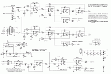
reader's amusement, the following schematic of a subwoofer crossover I have
been working on, along with a brief introduction and some electrical design
notes. If there is interest, I could follow up with some implementation notes.
INTRODUCTION
I looked at all the crossover designs I could find and found they all had their
drawbacks. Rather than enumerate them, I will point out what I believe are the
advantages of what I decided on.
The attached crossover is a two-way, 12dB/octave high pass, 24dB/octave low
pass design which explores the idea that parts are cheaper and easier by the
dozen -- both to get and to use.
It uses a combined high/low state variable filter for the first 12dB/octave to
reduce the number of different filter capacitors and tuning resistors and to
produce closer matching (more complementary) high/low responses. It also uses a
state variable filter to produce low DC offsets on the high pass outputs -- even
with NE5532 opamps and 20K tuning resistors -- to eliminate clicks.
The crossover sums the two bass channels which saves parts, both internally and
externally: you don't have to sum them elsewhere, or use a two-channel amp with
dual subwoofers or a subwoofer with dual voice coils.
The summed bass channel includes a subsonic/boast filter to eliminate rumble
and optionally compensate for the subwoofer's mechanical rolloff. It provides
complementary (quasi-balanced) line level outputs that can drive an
inexpensive, high-power studio amplifier.
Finally, the crossover includes a soft muting switch for silent muting,
dramatic effect, and nocturnal peace with the neighbors.
ELECTRICAL DESIGN NOTES
My first design for a subwoofer crossover was similar to Rod Elliot's Project P09
but with equal component value, Sallen-Key filters. The present design applies
what I learned from my first one, crossover P09, and a few other designs.
The design includes a subwoofer muting switch and a volume control. The latter
is still essential. I have a fairly old receiver that does not allow you to
re-inject a signal after the volume control. I also found this was true on some
current receivers.
The design use a commonly-available Alps RK27 volume control. Capacitors C1
and C4 (see attached schematic) prevent current from flowing through its
sliders which could cause silver ion migration and shorten its life. Placing
the capacitors after the control rather than before also lowers the low
frequency roll off.
The design uses NE5532s to carry full frequency range signals and drive
outputs. It uses TL072s in the subwoofer channel at frequencies well below the
point they show increasing distortion.
The 20dB (10x) gain stage (IC1) restores the signal to line level after the
volume control has attenuated it. This gives unity gain with the control about
halfway. I left out this stage in my first crossover and had noise problems. By
omitting parts and adding a few jumpers, you could delete the volume control
and have a simple, unity gain buffer.
The crossover implements the fourth-order, Linkwitz-Reiley crossover scheme
Linkwitz presented in his early Wireless World papers. It provides a summed
subwoofer channel and assumes you have a pair of acoustical suspension (sealed)
satellite loudspeakers. The design crosses over at the satellites' -3dB
point. The low pass output rolls off at 24dB/octave, the high pass outputs, at
12dB/octave, with the satellites' mechanical rolloff providing another
12dB/octave. Using the satellites to complete the L-R response produces less
overshoot and allows a lower crossover frequency. It may require, however, some
tweaking of the crossover point since the satellites don't exactly respond as
simple, second-order Butterworth filters.
IC2, IC4, and IC5 form a state variable filter that provides the first
12dB/octave of high and low pass filtering. I chose this topology because it
requires fewer tuning resistors or resistor values than a minimum parts count,
Sallen-Key design. It also allows all the tuning resistors to have the same
values when combined with an equal component value, S-K, low pass filter
(IC6A). A total of six, identical resistors set the crossover frequency so that
you need only buy, at worst, a few different values to match the crossover to
the satellites, and in packets of ten at a considerable discount.
The crossover uses 100nf or 150nF MKP capacitors to keep signal impedances
down. These tend to be fairly large (economical or available parts usually have
a 7.5-10 mm lead spacing) and relatively expensive. They can also be hard to
order in unit quantities. The design uses eight, identical parts to make them
easier to buy, or to make it easier to buy extras if you wish to select parts
and improve tolerances. This is another reason for the design's equal-value
tuning resistors: you can then afford a few extra resistor packs to tune the
crossover to the capacitors.
IC8A serves as a subsonic filter, or as a peaky, high-pass filter that
compensates for the subwoofer's rolloff. IC8A also removes the 100-400 mV DC
offset introduced by the first gain stages. This allows them to use an NE5532
rather than a fancier and more expensive part. The state variable filter's
balanced, low impedance (3.3K) summing point does a surprisingly good job of
reducing DC offsets in the satellite channels.
JFET Q1 and discrete colleagues allow panel switch S1 to silently mute the
subwoofer channel. The muting circuit also keeps the channel from
"motor-boating" as the power dies. The low and high pass outputs still emit a
harmless chirp at power down but I never hear it because of my receiver's power
sequencing.
The crossover provides a quasi-balanced output that can drive an inexpensive
studio/PA amplifier. You could also add a phase switch and use the normal and
inverted outputs to drive a consumer amplifier with close to unity gain. (No,
that wasn't planned -- things just came out that way!)
informative discussions I have read in these forums. I offer for the gentle
reader's amusement, the following schematic of a subwoofer crossover I have
been working on, along with a brief introduction and some electrical design
notes. If there is interest, I could follow up with some implementation notes.
INTRODUCTION
I looked at all the crossover designs I could find and found they all had their
drawbacks. Rather than enumerate them, I will point out what I believe are the
advantages of what I decided on.
The attached crossover is a two-way, 12dB/octave high pass, 24dB/octave low
pass design which explores the idea that parts are cheaper and easier by the
dozen -- both to get and to use.
It uses a combined high/low state variable filter for the first 12dB/octave to
reduce the number of different filter capacitors and tuning resistors and to
produce closer matching (more complementary) high/low responses. It also uses a
state variable filter to produce low DC offsets on the high pass outputs -- even
with NE5532 opamps and 20K tuning resistors -- to eliminate clicks.
The crossover sums the two bass channels which saves parts, both internally and
externally: you don't have to sum them elsewhere, or use a two-channel amp with
dual subwoofers or a subwoofer with dual voice coils.
The summed bass channel includes a subsonic/boast filter to eliminate rumble
and optionally compensate for the subwoofer's mechanical rolloff. It provides
complementary (quasi-balanced) line level outputs that can drive an
inexpensive, high-power studio amplifier.
Finally, the crossover includes a soft muting switch for silent muting,
dramatic effect, and nocturnal peace with the neighbors.
ELECTRICAL DESIGN NOTES
My first design for a subwoofer crossover was similar to Rod Elliot's Project P09
but with equal component value, Sallen-Key filters. The present design applies
what I learned from my first one, crossover P09, and a few other designs.
The design includes a subwoofer muting switch and a volume control. The latter
is still essential. I have a fairly old receiver that does not allow you to
re-inject a signal after the volume control. I also found this was true on some
current receivers.
The design use a commonly-available Alps RK27 volume control. Capacitors C1
and C4 (see attached schematic) prevent current from flowing through its
sliders which could cause silver ion migration and shorten its life. Placing
the capacitors after the control rather than before also lowers the low
frequency roll off.
The design uses NE5532s to carry full frequency range signals and drive
outputs. It uses TL072s in the subwoofer channel at frequencies well below the
point they show increasing distortion.
The 20dB (10x) gain stage (IC1) restores the signal to line level after the
volume control has attenuated it. This gives unity gain with the control about
halfway. I left out this stage in my first crossover and had noise problems. By
omitting parts and adding a few jumpers, you could delete the volume control
and have a simple, unity gain buffer.
The crossover implements the fourth-order, Linkwitz-Reiley crossover scheme
Linkwitz presented in his early Wireless World papers. It provides a summed
subwoofer channel and assumes you have a pair of acoustical suspension (sealed)
satellite loudspeakers. The design crosses over at the satellites' -3dB
point. The low pass output rolls off at 24dB/octave, the high pass outputs, at
12dB/octave, with the satellites' mechanical rolloff providing another
12dB/octave. Using the satellites to complete the L-R response produces less
overshoot and allows a lower crossover frequency. It may require, however, some
tweaking of the crossover point since the satellites don't exactly respond as
simple, second-order Butterworth filters.
IC2, IC4, and IC5 form a state variable filter that provides the first
12dB/octave of high and low pass filtering. I chose this topology because it
requires fewer tuning resistors or resistor values than a minimum parts count,
Sallen-Key design. It also allows all the tuning resistors to have the same
values when combined with an equal component value, S-K, low pass filter
(IC6A). A total of six, identical resistors set the crossover frequency so that
you need only buy, at worst, a few different values to match the crossover to
the satellites, and in packets of ten at a considerable discount.
The crossover uses 100nf or 150nF MKP capacitors to keep signal impedances
down. These tend to be fairly large (economical or available parts usually have
a 7.5-10 mm lead spacing) and relatively expensive. They can also be hard to
order in unit quantities. The design uses eight, identical parts to make them
easier to buy, or to make it easier to buy extras if you wish to select parts
and improve tolerances. This is another reason for the design's equal-value
tuning resistors: you can then afford a few extra resistor packs to tune the
crossover to the capacitors.
IC8A serves as a subsonic filter, or as a peaky, high-pass filter that
compensates for the subwoofer's rolloff. IC8A also removes the 100-400 mV DC
offset introduced by the first gain stages. This allows them to use an NE5532
rather than a fancier and more expensive part. The state variable filter's
balanced, low impedance (3.3K) summing point does a surprisingly good job of
reducing DC offsets in the satellite channels.
JFET Q1 and discrete colleagues allow panel switch S1 to silently mute the
subwoofer channel. The muting circuit also keeps the channel from
"motor-boating" as the power dies. The low and high pass outputs still emit a
harmless chirp at power down but I never hear it because of my receiver's power
sequencing.
The crossover provides a quasi-balanced output that can drive an inexpensive
studio/PA amplifier. You could also add a phase switch and use the normal and
inverted outputs to drive a consumer amplifier with close to unity gain. (No,
that wasn't planned -- things just came out that way!)
Attachments
Hi John F.
I did a commercial PA stereo 3 way xover with variable high pass treble/mid and subtractive bass. Lots of two pole compd 301s - in 1975.
I also did a commercial "Bass Extender" - a simple Q=2 pot tunable filter which with a retuning sleeve for the loudspeakers could extend the bass to 0.6 and 40dB subsonic filtering in 1989.
Lots of chips in yours but chips are cheap especially 5532s and TL072s . Will you Class A bias them all?
Personally I find the 5534/2 'dark' sounding and would much rather use a good FET input chip - trouble is the ones with good CMRR and PSRR are up there!
richie00boy said:Nice idea, similar to something I worked on. You just need to give people your layout now
That could be arranged if there is enough interest in yet another active
L-R crossover PCB layout.
As you might have gathered from just the schematic,I had a lot of fun working on this project, improving things I had tried before
and applying old ideas in interesting and neat ways.
I sent a copy of the muting scheme to EDN and they published it (that paid for
the PCBs) and then a copy to Siegfrid Linkwitz, to thank him for all I have gotten
out of his articles. (He liked it.) Douglas Self even took a quick look at the
crossover's supply layout after I wrote him to make sure I understood his
V+ to V- decoupling scheme. This is crazy. I have spent so much more time
designing and programming things that only use two states. I had forgotten how
much fun audio can be!
amplifierguru said:Lots of chips in yours but chips are cheap especially 5532s and TL072s . Will you Class A bias them all?
Hmmm. I didn't know I could choose to do that when working with these op amps, but then I am largely a digital guy used to thinking in two states. (Perhaps that also explains all the chips.
)Personally I find the 5534/2 'dark' sounding and would much rather use a good FET input chip - trouble is the ones with good CMRR and PSRR are up there!
I have socketed the op-amps and probably added more bypass and compensation capacitors than they need, just so that I can experiment. If nothing else, I am curious if Mr. Self's decoupling scheme will accomodate higher speed op-amps. Would you suggest the 10x gain stage op-amps might be the first I try changing?
Hi JohnF
I would say try an LF357 in your 20dB first stage but they're singles. It's a decompensated (reduced miller capacitance) LF356 and as a result has faster slew rate (less current to charge and discharge C) and improved CMRR and PSRR over it's fully comp sibling. Result :lower THD and better resolution at HF from improved CMRR.
Still the OPA637 is streets ahead (a decomp 627) and clearly audibly superior.
I recall rechipping a RANE crossover for a friend and used a LT1057 from memory. Check out LT's offerings. If you can set up a high res system to listen through just one stage it should prove definitive.
- Status
- This old topic is closed. If you want to reopen this topic, contact a moderator using the "Report Post" button.
- Home
- Amplifiers
- Solid State
- Another 2nd/4th-order L-R active crossover