Here is another thought on regulated power supplies on power amps.
1) If you look at many implementations of biasing on a class-A amp, it is regulated. Typically, the reference current will be generated off a regulated supply. A current multiplier will then be used to generate the main bias current for the output stage. The output current of this will be somewhat independant of the supply rails.....hence a current regulated output.
2) If you regulate the output voltage of a power amplifier, you have essentially created a feedback loop that uses the output of the audio signal as an input. As the voltage of the output drops, which will be a function of the audio output (or input if you want to think it that way), the current into the pass transistor increases, yada, yada, yada......
In either case, the output of the regulator can be modelled as a function of the audio signal and yes, it can be a source of distortion. The question is, is this source of distortion, when worked upon by your amplifier circuit, worse or better than having 60Hz or 120Hz from an un-regulated supply?
Alvaius
Re: Forgot one
OPA445, +/-45 V rails.
Jan Didden
HarryHaller said:The schematic is from:
“A Power Supply Regulator For the Adcom GFA-555,” Kit Ryan, The Audio Amateur4/89
"Slap on a couple of opamps and you would really have a winner..."
If you can find on op amp with +/- 35 volts rails!
OPA445, +/-45 V rails.
Jan Didden
What causes the temperature to rise with the rectifiers and transformer?
Simply, I2R losses in those devices.
It's exacerbated by the reduction in conduction angle of the rectifier diodes as a result of using lots of capacitance and very little current drain in preamp applications.
I strongly suggest you try the same PSU with only 1 15,000 cap and then see how it sounds - I suspect you'll find it sounds much better, rythmically.
Andy.
Bridge rectifier life expectancy when run hot?
Thanks for your 2 cents
But the PSU is built for the mono power amp..
I strongly suggest you try the same PSU with only 1 15,000 cap and then see how it sounds - I suspect you'll find it sounds much better, rythmically.
Thanks for your 2 cents
But the PSU is built for the mono power amp..
Regulated supplies
Hey Chris,
Not so fast... ALW is right, the same reasoning goes for power amps, although the numbers obviously will be different from the pre-amp case. Those insane reservoir caps of 50.000 or 100.000 or more uF give rise to 50 Amps or more sharp current peaks, and very high levels of harmonics to the power line freq in your amp. I'd rather have some 60 and 120 Hz benign ripple, which the amp can handle perfectly, thank you, instead of a spectrum into the 10s of Khz that is much harder on the amps PSRR.
Cheers, Jan Didden
ALW, Jan
Thanks for the advise. I'll try remove 2 of those 15,000uf caps from each supply rail and listen for the difference. If it turns out good there will then be 8 of these capacitors left over for other projects or more amps for bi-amping later I hope. That's good news for me for those caps cost approx. $45 Canadian each. (16 pounds sterling each plus tax and shipping and custom clearing broker fees)
Will it also reduce the heat generated by the bridge rectifiers you think by reducing the capacitance in the rails?
Now then how about those marketing speech trying to sell the upgrades of their amps to increase the caps even as high as 120,000uf? Are they just trying to sell more parts or there is some good reason behind the upgrade? So what would be the nominal capacitance for smooth caps in generic PSU.. 10,000uf?
Chris
chris ma said:ALW, Jan
Thanks for the advise. I'll try remove 2 of those 15,000uf caps from each supply rail and listen for the difference. If it turns out good there will then be 8 of these capacitors left over for other projects or more amps for bi-amping later I hope. That's good news for me for those caps cost approx. $45 Canadian each. (16 pounds sterling each plus tax and shipping and custom clearing broker fees)
Will it also reduce the heat generated by the bridge rectifiers you think by reducing the capacitance in the rails?
Now then how about those marketing speech trying to sell the upgrades of their amps to increase the caps even as high as 120,000uf? Are they just trying to sell more parts or there is some good reason behind the upgrade? So what would be the nominal capacitance for smooth caps in generic PSU.. 10,000uf?
Chris
As for the reasoning behind those upgrade cap banks, you should really ask the guys who sell them.
As for generic cap, I normally use 1000 or 2000 uF per ampere load current, worst case. In my experience, more than 22.000 uF seldom gives improvements.
Jan Didden
Peter Daniel said:I've also heard that too much caps may slow the amp, but never did any comparisons. Would be interested to hear results.
With the gain clones it has been found that the amps don't sound as good with too much C. 1,000uF seems to work best.
dave
Instead of throwing away caps
One of the reasons why REALLY big transformers are needed in high-end equipment is the short conduction angle.
Try using a series resistor to increase the conduction angle. This can be done at transformer OR between banks. I would try a small bank followed by an RC large bank.
Petter
One of the reasons why REALLY big transformers are needed in high-end equipment is the short conduction angle.
Try using a series resistor to increase the conduction angle. This can be done at transformer OR between banks. I would try a small bank followed by an RC large bank.
Petter
series resistor?
Peter,
Can you specify some RC values and component layout please. Are you suggesting there is no need to reduce the capacitance of my PSU?
Peter,
Can you specify some RC values and component layout please. Are you suggesting there is no need to reduce the capacitance of my PSU?
Try using a series resistor to increase the conduction angle. This can be done at transformer OR between banks. I would try a small bank followed by an RC large bank.
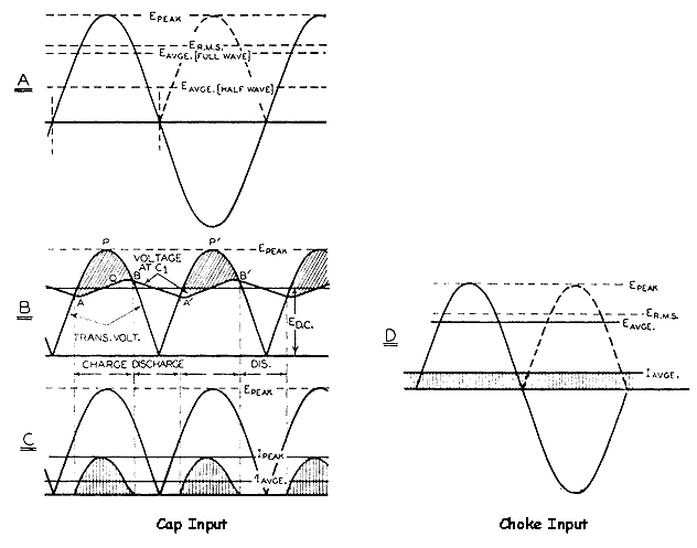
Using a transformer/rectifier/cap method is one of the crudest ways to get dc from ac that exists. It is like trying to levitate your body by being continually kicked up your backside. Some decades ago choke regulators were fashionable. I suppose the economics of silicon caused the demise of the choke. Choke regulators smooth the rectified current pulses whilst conserving energy (a resistor shunt wastes power). The disadvantage is cost and space and a more complicated design equation.
BAM
BAM
Hold on, part II
I've found that adding series resistors is detrimental too, although I've not done significant experiments.
There was an obvious reduction in noise, but the sound was more than a little dull and unexciting to listen to.
Yaaawn...
I have a little theory (that I'm keeping to myself at present ) that relates capacitor size to transformer parameters.
It seems to work for all the designs in which I've tried it, but finding optimal capacitor values in PSU's gets expensive.
I've one to build soon and will be trying caps either side of my calculated value - if it works I may reveal more. The problem at the moment is I don't understand the mechanism by which the degradation arises.
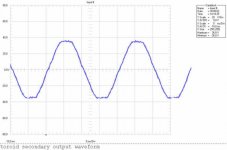
I can't obviously measure the effect, yet I can hear it. It may be related to the waveform on the secondary - take a look at it with large caps in place - not really sinusoidal at all. This flat-topping gives some harmonic content we don't want, but adding series R before the caps doesn't improve the sound, just changes it.
A.
I've found that adding series resistors is detrimental too, although I've not done significant experiments.
There was an obvious reduction in noise, but the sound was more than a little dull and unexciting to listen to.
Yaaawn...
I have a little theory (that I'm keeping to myself at present
) that relates capacitor size to transformer parameters.It seems to work for all the designs in which I've tried it, but finding optimal capacitor values in PSU's gets expensive.
I've one to build soon and will be trying caps either side of my calculated value - if it works I may reveal more. The problem at the moment is I don't understand the mechanism by which the degradation arises.
I can't obviously measure the effect, yet I can hear it. It may be related to the waveform on the secondary - take a look at it with large caps in place - not really sinusoidal at all. This flat-topping gives some harmonic content we don't want, but adding series R before the caps doesn't improve the sound, just changes it.
A.
Bam
About the best description I've read yet
I've been meaning to try choke reg's - you've just spurred me onto trying it, along with another chat I had recently with a designer about the lost art of inductors!
Will report back when I try it.
A
Using a transformer/rectifier/cap method is one of the crudest ways to get dc from ac that exists. It is like trying to levitate your body by being continually kicked up your backside
About the best description I've read yet
I've been meaning to try choke reg's - you've just spurred me onto trying it, along with another chat I had recently with a designer about the lost art of inductors!
Will report back when I try it.
A
Report Sir
Andy is right (ALW), Thanks.
I removed two 15,000uf from the rails, each rail now has one BHC Aerovox ALT22A 15,000uf 63V and bypassed by three 100nF polypropylene caps left on the rails. Kept everything else the same as before.
The sound of the amp changed ;
Treble now has more dynamic and forward, cymbal sound better than before, I do not know how to describe it but it sound clearer overall from mid to high frequency. The amp seems to be a bit more sensitive, but then it seems a little thin, more airy around instruments. Actually there is one track on a old CD clipped badly with high frequency during a particular short loud passage of the song. May be just the bad recording I do not know.
But the heat of the bridge rectifiers and the transformers got just as hot as before though. No luck there.
Andy, once you have found the optimum cap & tranny formulae please share with us...
Regards,
Chris
What about the bass?
I don't think that amount of capacitance has anything to do with the bridge temp. Once the caps are charged the current draw from the amp influences the bridge's temperature. Just put it on a heat sink and forget that it's hot. I placed my bridges on the same heatsink as output devices and they were around 55 deg.
I don't think that amount of capacitance has anything to do with the bridge temp. Once the caps are charged the current draw from the amp influences the bridge's temperature. Just put it on a heat sink and forget that it's hot. I placed my bridges on the same heatsink as output devices and they were around 55 deg.
Bass? Not much changed that I can hear yet..
At first I thought the bass was reduced (first impression) right after the modification ; due to the more dynamic mid high caught my attention, then I turn my attention to the bass and ignore the mid high of a couple of recordings that I know best, is all there, just as same as before the mod.
I'll give it a couple of days listening then I will put one cap back per rail (2 X 15000uf per rail) to check the result. For now there are certain tracks it sounds just a little bit too bright in the vocal department for my liking. Mind you the cymbal and hi-hat sound great now. The track Ready for love by Bad Company sound really good with the drums now, used to sound a bit strangled, bass stays the same however, did not have time to listen to my reference CD yet the Sheffield test cd titled "My Disc". Will do that tonight.
Real-world picture:
planet 10.
I get very nostalgic when I see such a textbook picture.
This is what I've measured during the test of my LDO-regulator today:
Perhaps the phenomena in question has something to do with the relationship of the inductance of the secondary - the resistance from the secondary to the capacitors - the capacitance - and the waveform ??
Attachments
- Status
- This old topic is closed. If you want to reopen this topic, contact a moderator using the "Report Post" button.
- Home
- Amplifiers
- Solid State
- Regulated Power supplies