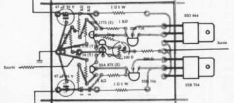
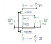
njepitt said:OK, here's a drawing of the circuit I'm using. I didn't put on the values of the bias resistors, since I'm using trimpots for these (at least for the time being). These are adjusted to give 550mA bias, as the Monstre articles recommend. (Although I suppose the recommended value depends on the output transistors too, right?).
I don't use PCBs (at least not yet), all done p2p.
It's not too hard to reduce the resistors on either side of the trimpot (which would reduce it form 460R to, say, 300R). What do you think?
Cheers
Nigel
regarding "loudness" ( gain ) issue - double check values of 220 and 10 ohms resistors in feedback net ,same as functionality of feedback net ( is it connected at all , where it need to be ) .
excessive gain and noise are signs that you're running that amp open loop ........ and fact that you have same culprit in both channels is sign that you made some system mistake ... (not connected track or similar)
actually, to support what Zen mod says,
I remember there is some trick with the location of the 10 Ohm resistor
its location is shown incorrectly on the pcb overlay pic layout in the class a amplifier site and should be connected as per the circuit diagram.
(that is from the pot wiper to earth)
-Dan
I remember there is some trick with the location of the 10 Ohm resistor
its location is shown incorrectly on the pcb overlay pic layout in the class a amplifier site and should be connected as per the circuit diagram.
(that is from the pot wiper to earth)
-Dan
Thx for the replies. I'm not sure what "open loop" means... Am I right in guessing it simply means the feedback loop isn't working? (which is the second half of ZenMod's reply) Anyone have a reference where I can read up? Certainly I can (and will) check the remarks about the 10R and 220R resistors, and the feedback circuit as a whole.
Returning the trimpot to 100R sounds a backwards step - after all things sounded dreadful before raising it. The original circuit (which uses Y grade jfets) uses 100R, other circuits I have seen using GR grade use 200R. I simply guess-timated the value. Reducing it to 200-300R sounds a more plausible thing to try.
Nobody seems to think the output transistors are the culprits, right?
I'll report back.
Cheers
Nigel
@njepit :
simply check have you proper conection of 220R and 10 R , between output and trimpot ( between sources of jfets )
open loop - means - disconnected feedback net ( 220r-10R - pot ) , when amp have entire possible gain ..... , not decreased with feedback .....
in that case - you'll have excessive gain and noise
if you have feedback connected as needed , any swap of output transistors will have just diminutive influence , not massive one .....
Zen Mod said:@njepit :
simply check have you proper conection of 220R and 10 R , between output and trimpot ( between sources of jfets )
open loop - means - disconnected feedback net ( 220r-10R - pot ) , when amp have entire possible gain ..... , not decreased with feedback .....
in that case - you'll have excessive gain and noise
if you have feedback connected as needed , any swap of output transistors will have just diminutive influence , not massive one .....
Thanks ZenMod. Very clear explanation. I'm checking the 220r -20r network as I write this....
Two questions - the trimpot is evidently part of the feedback circuit. Presumably its value therefore affects the feedback loop. So if it's value is to high there is too little feedback. Would this have the same kind of effect (although to lesser degree) as no feedback? That is, force the amp into higher gain than is desired? The second question if what happens if the two bias resistors are unbalanced? This may be an issue since I am using trimpots.
Cheers
Nigel
hiraga class a amp
Hi! I'm new here, but 4 yrs ago i built this amp, but finding the parts is like needle in the haystack, but its worth it, very open, very natural. big factor is the power supply, instead i use capacitance multiplier i got from Rod Elliots site. HUm was eliminated. But what really gave me goosebumps is when i built the 1969 version of JLH modified to dual rails by Rudy van Stratum. I still use this amp to this day, my HIRAGA was now in the hand of a friend as a gift. When he tried the HIRAGA his commercial amp is now in his shelves, collecting dust.
Hi! I'm new here, but 4 yrs ago i built this amp, but finding the parts is like needle in the haystack, but its worth it, very open, very natural. big factor is the power supply, instead i use capacitance multiplier i got from Rod Elliots site. HUm was eliminated. But what really gave me goosebumps is when i built the 1969 version of JLH modified to dual rails by Rudy van Stratum. I still use this amp to this day, my HIRAGA was now in the hand of a friend as a gift. When he tried the HIRAGA his commercial amp is now in his shelves, collecting dust.
njepitt said:Hi Dan,
Yes, I realised the 2N5462 wasn't ideal - I used it in the first version simply because it was what I could get my hands on. Now that I have 2SK170 and 2SJ74 (BL grade) I am using these in the second (now third) version.
Since I posted I have also isolated another possible problem. The trimpot I am using is 100R, which according to some posts above is correct for the Y grade jfets, but too low for the BL grade (which have higher Idss...). So I am going to pop in two fixed resistors on either side of the trimpot to see what difference this makes. (I am guessing at 100 to 180R on each side to give a total of 300 to 460 R on the trimpot).
I am a little confused by your remark about Cob of the Toshibas. The datasheet for the 2SB754 (which is the original device) gives typ. 300pF, whereas the 2SC5200 shows typ. 200pF... While out component shopping I picked up two pairs of MJW3281/1302 to try in place of the 2SC5200/1943, but I see from the datasheet that their Cob is higher still (max 600pF is given). Worth trying? (You are certainly correct that the power rating of the 2SC5200/2SA1943 is far higher than necesssary here. I used them because I had them....)
I'll send you a PM about your original transistors.
Cheers
Nigel
The MJE15030 could be used ?
I have made a few alterations - not more than tweaks, really. I have reduced the value of the central trimpot to 200R, and used a great deal of care in making sure the bias resistors were of the same value. ( I am using trimpots for these too, remember.) This reduced the problem to more reasonable levels. Background hum/noise with no signal and full volume is only really audible with ear close to speaker, and there is no clear distortion or anything else obviously wrong. Gain is still greater than the other Monstre, but again, not obviously wrong. (ZenMod: I checked the feedback circuit carefully - no error there, unless it is the value of the trimpot itself.)
So I have finished all the tweaks I can do, and still find myself unsatisfied with the sound. It's not so much that it sounds bad (which it doesn't, really), it's that I expected it to sound better. Since I invested in the right jfets, and better components and so forth, I expected it to sound closer to my F5 than to the older Monstre. So I suspect I'm not going to get this version of the amp much better. I suspect that:
1. The chassis/case on the first version screens from interference better than the second.
2. The earth connections on the first version are (somehow) superior in reducing mains hum.
3. Factors 1 and 2 matter more than the quality of the components. (At least in this case...)
I'd be interested in putting together a Monstre with original transistors (Dan: I tried a PM but the site wouldn't let me; if you write to my e-mail I can reply...). I'd also be interested in other amp designs to consider instead, but maybe that's another thread. But, I'm out of ideas on this present version, unless anyone has a suggestion?
In any event, many thanks for your contributions.
Cheers
Nigel
Hi Nigel,
I will send an email, i really think you will benefit from original transistors.
I am in the process of matching some sets at the moment.
have been matching like a madman lately.....
so far have matched
2SA872A(E), 2SC1775A(E), 2SB716, 2SD756,
I am matching the 2SJ74(BL) and 2SK170(BL) today hopefully...
-Dan
Sorry nigel i could not access your email from your info.
Here is my email:
danw1million@hotmail.com
-Dan
Here is my email:
danw1million@hotmail.com
-Dan
Dan, if you are using BL grade jfets, what value of trimpot did you use? I wonder if it's worth reducing 200R right down to the original 100R, which was for Y grades?
By the way, anyone have an easy home-brew method for measuring amp output? It would be interesting to see which of the Monstres are closer to the 8W it "should" be...
Cheers
Nigel
By the way, anyone have an easy home-brew method for measuring amp output? It would be interesting to see which of the Monstres are closer to the 8W it "should" be...
Cheers
Nigel
Hi Nigel,
There are three grades listed on the datasheet i have. and they relate to the Idss characteristics.
Correct me if i am wrong but perhaps the "V" is a typo and should be "Y"
the BL grade batch i have at the moment are in majority over 10mA Idss (luckily)
so they fall within the overlap of the 6-12mA - 10-20mA Idss.
I used the original value for the trimpot.
-Dan
Hi Dan,
I am not sure which letter you think is a typo, but in my post above I definitely meant "Y", which I think is the original grade Hiraga specified. As I understand things (please correct me if wrong) the Idss grades are lowest for "Y", increasing in sequence for "GR", "BL" and "V". (The last three are confirmed on the 2SK170 datasheet I just googled, I can't confirm the "Y" right now.) "BL" are the only ones I have on hand.
In your email you mention 2SA1186/2SC2837 as output transistors - Have you used these already? I wonder if it's worth trying them in my present version? I would still like to knwo why the gain is higher.... Maybe reduce the trimpot to 100R and try out these output trans.??
Cheers
Nigel
njepitt said:Hi Dan,
I am not sure which letter you think is a typo, but in my post above I definitely meant "Y", which I think is the original grade Hiraga specified. As I understand things (please correct me if wrong) the Idss grades are lowest for "Y", increasing in sequence for "GR", "BL" and "V". (The last three are confirmed on the 2SK170 datasheet I just googled, I can't confirm the "Y" right now.) "BL" are the only ones I have on hand.
In your email you mention 2SA1186/2SC2837 as output transistors - Have you used these already? I wonder if it's worth trying them in my present version? I would still like to knwo why the gain is higher.... Maybe reduce the trimpot to 100R and try out these output trans.??
Cheers
Nigel
Sorry i was not clear, I meant in the shcematic the "Y" might be a typo. because the normal (as you have seen) groupings for the j74/k170 is GR, BL and V. per the datasheet.
i think perhaps the original article has a type and Y should be V???
I have not yet tried the 2SA1186/2SC2837 combo.
currently you are running if i am not mistaken:
2SK170BL, 2SJ74BL
2SC2240, 2SA970
BC640, BC639
2SC5200, 2SA1943
this is what i think after briefly looking at the data sheets.
2SK170BL, 2SJ74BL should function well.
2SC2240, 2SA970 relatively similar if hfe is selected appropriately
BC640, BC639 hfe is much to low (in my opinion)
2SC5200, 2SA1943 should function well.
-Dan
- Home
- Amplifiers
- Solid State
- Hiraga "Le Monstre"