Nice to see this topic still actual.
I almost finished my own little monster after years of delay.
I designed a very tiny switch on/off circuit which also controls the batteries to switch on when the voltage over the second part of capacitors rises above 13,2 V and only when the batteries are connected
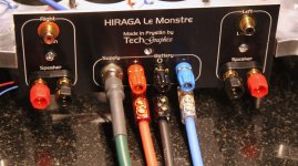
The pink on the photo is actual clear blue to the human eye: a number of blue LEDs embedded in the frontpanel will give it a blue "ambilight" when on..
The wooden covers, on and below the 15mm thick aluminium middleframe will be made from American Black walnut..
Kees
WOW! That is beautiful. Quite a remarkable build, congrats!
- 2nd Stage - BC327/337
Try BC489/490 if you can get them.
Or 2SD667/2SB647.
I'm not fond of the 327/337 types...
Nice to see this topic still actual.
Do you sell it?
If so send a pm.
Hello Audiomanics,
Thats an amazing buid.
@ craigtone, very nice PCB incorporating everything.
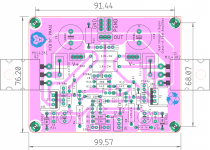
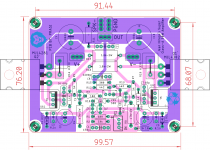
@ SanjeevM, I am already working on the layout and here it is almost final. I have provided zobel option and input ground lift.. Even TO-3 devices can be mounted via short wires on aluminium angle on the same vertical heat sink of 3" length.
regards
prasi
Thats an amazing buid.
@ craigtone, very nice PCB incorporating everything.
@ SanjeevM, I am already working on the layout and here it is almost final. I have provided zobel option and input ground lift.
. Even TO-3 devices can be mounted via short wires on aluminium angle on the same vertical heat sink of 3" length.regards
prasi
Attachments
Hello guys,
here are the pdfs and gerbers.
Regards
Prasi
After a short listening i must share my finding.
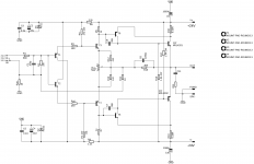
What is the used transistors.
J1=2sk246
J2=J103
T1=bc550c
T2=bc560c
T3=2sa1837
T4=2sc4793
T5=MJL3281A
T6=MJL1302A
R3=2k2//1k multi turn
R4=2k2//1k multi turn
I have test other transistor combination BUT stay away from high voltage transistors as ksa992, ksc1845 for the ccs, T1, T2.
I spend all the day trying to understand why one chanel playing so different, no bass.
Now i know... T1, T2 bc550, 560.
Thimios, are these the modern equivalents to be used with the board that prasi posted above? Thank you.
Nice to see this topic still actual.
I almost finished my own little monster after years of delay. .......
Kees
Hi Kees.
Very attractively done ....
Congrats & enjoy music (every musical note).
Allez, salukes.
Karel
(happy owner 2x4monster)
...Appelscha...
That's a 167 km distance.
A while ago I took over a Hiraga 8W diy but lousy build.
Some tweaking / adjusting neccessary. Simple one switch black box.
It's just what you want.. I have quite a "mancave" and i know how to build things decent. I propose a rebuild with design..
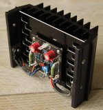
On my little monster are some unique, hard or not to get items, like, for instance, the heatsinks: these are taken from one of the obsolete Philips Matchline CRT-tv from the 80's.. I had one for many years and recently i could lay my hand on another one.. I couldn't find any heatsink-manufacturer (like Fisher etc) that had a similar model in production. My projects are almost always unique and even i couldn't build a second because of parts made from "unobtainium"
But if you're interested: send me a PM with your mailaddress and maybe your phonenumber.. we can discuss it further in Dutch..
Kees
Gerbers and stuff.Hello Audiomanics,
Thats an amazing buid.
@ craigtone, very nice PCB incorporating everything.
@ SanjeevM, I am already working on the layout and here it is almost final. I have provided zobel option and input ground lift.
regards
prasi
Attachments
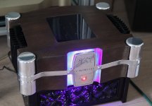
almost finished.. Unfortunately, the big mill broke some parts from the lower cover so I have to redo that..
And again.. the pink light is actually just blue.
Kees
Beautiful work Kees
almost finished.. Unfortunately, the big mill broke some parts from the lower cover so I have to redo that..
And again.. the pink light is actually just blue.
Kees
Kees that is wonderful! Really thought out and well built congratulations, wish i had access to a milling machine and a lathe.
It's finished a few weeks already and plays every day, all day.. i'd like to share another few photo's from the inside and the diagram of the push-on-push-off circuit and delayed Battery switch-on (which only works when the batteries are connected..
Kees
Kees
Attachments
-
 monstertje2.JPG103.8 KB · Views: 275
 -
 Kabels.JPG137 KB · Views: 198
 -
![CX3C1229[1].JPG](/community/data/attachments/726/726610-968cdbbb36f6b33ae28b853a4c5d54d0.jpg) CX3C1229[1].JPG79 KB · Views: 214
CX3C1229[1].JPG79 KB · Views: 214 -
![CX3C1226[1].JPG](/community/data/attachments/726/726608-55af98bd575cd587f312bff9d84d779b.jpg) CX3C1226[1].JPG113.4 KB · Views: 198
CX3C1226[1].JPG113.4 KB · Views: 198 -
![CX3C1225[1].JPG](/community/data/attachments/726/726605-b43b88ab77feb930c26998894c568fad.jpg) CX3C1225[1].JPG56.9 KB · Views: 236
CX3C1225[1].JPG56.9 KB · Views: 236 -
![CX3C1224[1].JPG](/community/data/attachments/726/726603-b0daff3ecf972c37094ba65bfde6c854.jpg) CX3C1224[1].JPG173.5 KB · Views: 244
CX3C1224[1].JPG173.5 KB · Views: 244 -
![CX3C1223[1].JPG](/community/data/attachments/726/726596-7fe78f2a17aa6d3bdf7a546466d1f204.jpg) CX3C1223[1].JPG147.9 KB · Views: 237
CX3C1223[1].JPG147.9 KB · Views: 237 -
![CX3C1222[1].JPG](/community/data/attachments/726/726589-8799263f924bb7b4e6768f01c8ab750f.jpg) CX3C1222[1].JPG112.8 KB · Views: 261
CX3C1222[1].JPG112.8 KB · Views: 261 -
![CX3C1221[1].JPG](/community/data/attachments/726/726584-d89922b4337297765c299893a62acb60.jpg) CX3C1221[1].JPG94.2 KB · Views: 623
CX3C1221[1].JPG94.2 KB · Views: 623 -
 DADU.jpg106.6 KB · Views: 637
Original but still not original
Hi all, I have a minor issue with my Le Monstre that I bought second hand from Netherlands some 10 years ago.
It has the original output stage with 2sd844 and 2sb754 but..... the power supply is defenitely not original, not even resembling the original power supply. Well, maybe the transformer is ok but the rest is a mix of caps from different eras and not even close to 300 000uF in total. I want to change this now cause I want to hear what the amp can do with proper feeding.
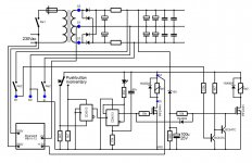
My idea is to use the medium stage power supply according to the shown picture (taken from the original article in le Audiophile) but I need help implementing the batteries.

When you build the big power supply it is clear that you implement car batteries which connect when the main is disconnected via a fourway switch but when you implement this smaller power stage (still going to have 2 x 12V 12Ah batteries and 2 x supercapas 0.47 F) there is no clear picture how to implement these batteries.there is no schematics for this stage.
Can I get some help scetching this implementation I would be very greatful cause I am not shure if the batteries should be switched into use or used parallell with the caps without any switch and if so.... will they serve as superbig caps or will they have to be charged separately and then connected via a switch.
I really want this to be close to the original while the output stage is still original cause it will come a day when I have to rebuild the whole amp and it will never be the same again.
Please, need the help since I am not able myself, I just know how to duplicate the schematics via physical work onto a pcb, not how to do the schematics themselves.
Sorry, forgot to say that I intend to use two separate feeds (mono) so in total 12 x 68000 uF plus the supercapas.
Hi all, I have a minor issue with my Le Monstre that I bought second hand from Netherlands some 10 years ago.
It has the original output stage with 2sd844 and 2sb754 but..... the power supply is defenitely not original, not even resembling the original power supply. Well, maybe the transformer is ok but the rest is a mix of caps from different eras and not even close to 300 000uF in total. I want to change this now cause I want to hear what the amp can do with proper feeding.
My idea is to use the medium stage power supply according to the shown picture (taken from the original article in le Audiophile) but I need help implementing the batteries.
When you build the big power supply it is clear that you implement car batteries which connect when the main is disconnected via a fourway switch but when you implement this smaller power stage (still going to have 2 x 12V 12Ah batteries and 2 x supercapas 0.47 F) there is no clear picture how to implement these batteries.there is no schematics for this stage.
Can I get some help scetching this implementation I would be very greatful cause I am not shure if the batteries should be switched into use or used parallell with the caps without any switch and if so.... will they serve as superbig caps or will they have to be charged separately and then connected via a switch.
I really want this to be close to the original while the output stage is still original cause it will come a day when I have to rebuild the whole amp and it will never be the same again.
Please, need the help since I am not able myself, I just know how to duplicate the schematics via physical work onto a pcb, not how to do the schematics themselves.
Sorry, forgot to say that I intend to use two separate feeds (mono) so in total 12 x 68000 uF plus the supercapas.
Last edited:
- Home
- Amplifiers
- Solid State
- Hiraga "Le Monstre"