
(Sorry for not posting this in English but the guys are from my neck of the woods ") )
)
Iskreno, na vasem mjestu bi se rijesio SA-100 cim prije (citaj: jucer). Tesko mi je naci ma i jedan pozitivan komentar o tom pojacalu, pocevsi od cinjenice da je transformator 2x premalen za snagu koju deklariraju, da napajanje za grijanje redovito spali plocicu i iskuha vlastite filter kondenzatore, da se radi strujnog pika prilikom ukljucenja MOSFET-i mogu sami od sebe spaliti (a vec se odavna ne proizvode), do toga da se jedna od trioda uopce ne korsiti a mogla je linearizirati ulaz. S manje dijelova se moglo napraviti puno bolje pojacalo - ovo sto je sad, bi se najbolje moglo nazvati izoblicilo.
Za poblize podatke ilimznAThotmailDOTcom...
)Iskreno, na vasem mjestu bi se rijesio SA-100 cim prije (citaj: jucer). Tesko mi je naci ma i jedan pozitivan komentar o tom pojacalu, pocevsi od cinjenice da je transformator 2x premalen za snagu koju deklariraju, da napajanje za grijanje redovito spali plocicu i iskuha vlastite filter kondenzatore, da se radi strujnog pika prilikom ukljucenja MOSFET-i mogu sami od sebe spaliti (a vec se odavna ne proizvode), do toga da se jedna od trioda uopce ne korsiti a mogla je linearizirati ulaz. S manje dijelova se moglo napraviti puno bolje pojacalo - ovo sto je sad, bi se najbolje moglo nazvati izoblicilo.
Za poblize podatke ilimznAThotmailDOTcom...
anatech said:Hi ilimzn,
Can you give us the readers digest version?
-Chris
Well, more or less what i mentioned about it in the other thread...
I got mine as a fixer, not surprisingly with a cooked transformer. I guess someone decided to believe the hype and try driving electrostatics with it or some other difficult load. Too bad there's nothing subjective about P=V * I * cos(phi) - you can't get 100WPC x 2 from a ~~200VA transformer... never mind that it boasts to be 'dual output' and in fact has the outputs connected together inside the transformer shell, but this amp would not even have to be a perpetuum mobile to stand up to its' specs, but even better: 200% or so efficiency
The filament power supply is downright comical. Whoever designed it has no idea what ripple currents are - placing the series resistor before the rectifier saves both rectifier and capacitors from cooking, and presents a better filter too (and yes, they do cook, and they do not filter overly well either).
Designers obviously also do not believe in regulated power supplies.
They do believe in not using one triode out of the 4 per channel, when the remaining one could have been used in a number of successful ways (active load, for instance), at least for the version i had (obviously different than the one in the schematic, perhaps a lower gain option?). Even the one in the schematic is quite od with regards to feedback, which is DC even though coupling of the stages is AC. Output stage on it's own must contribute some 0.5 - 1% of distortion and it's not the nice kind either. 10N12 and 10P12 are not very complementary...
The whole bias and offset setup starting with it's power supply (limiting the output to about to +-35V or so instead of limiting the gate voltage for all conditions) is odd, to say the least.
Etc etc.
The same parts (or less) could have been used to make a better amp...
 Yours sounds like an SA-12 where the follower driving the fets is in parallel (both sections). I can't agree with you more!
Well, it did say SA100 on it...
As for listening tests... hm, I'm trying hard to find polite words here.
In the end, I decided to do the following:
I used the high power output of my DAC (this can drive my 600ohm headphones directly at negligible distortion levels) as the input to the SA100, and gave the SA100 a pure non-inductive 8 ohm load. It was tapped at one point to alow me to listen to it through the same headphones at effectively zero amplification, via a switch. The switch cuts in a spare set of the same headphones I have as a load to the point (input or output) that I am not listening to, so that things as much as possible stay the same. I just wanted to be fair, I guess.
Now, the input (= DAC output) sounds the way I am used to hearing whatever it is I am playing. The output of the SA100, with this simplest possible load sounds TOTALLY AND UTTERLY different. You would have to be deaf not to hear that. And no matter how carefully I adjusted it to factory spec, or tried to tweak the bias current. Now, whatever differences you hear this way are entirely artifacts of the amp, and by definition they are distortion. I am sorry if this offends anyone, but to me it sounded just plain WRONG, incredibly inaccurate, and unpleasant.
Since I got it as a fixer, before I even listened to it for the first time, I ended replacing the transformer with 2 transformers, one for the output and one for the tube stage incl heaters, the power output one was a 400VA alone. The mod made the whole amp twice as heavy and barely fit inside, both were on rubber mounts. I also corrected the heater supply. The amp already came with a matched set of E88CC by Telefunken. I also added minor changes to other parts of the power supply (bypassed electrolytics with foil caps).
Listening was such a dissapointing experience I felt sorry for wasting good parts and could not get rid of it fast enough.
The funny thing is, the person who bought it told me that it was the best sounding SA100 he ever heared and he even tested the tubes and found them to be incredibly well matched and probably worth half the price he paid. I really could not take his praise as any kind of a compliment. At one point I was very close to just pulling the whole thing apart and re-doing it from scratch, but I decided it was just not worth it, which is why I sold it.
I still wonder how the manufacturer even sold any at all.
Oh, and BTW mine did not have a primary side fuse at all. It's a wonder it didn't burn a house to the ground when the transformer cooked...
The designer only uses Plitron, with no electrostatic sheiding.
When the HV transformer was installed separately from the main supplies, the regulation was much improved. That's why it was the best sounding unit the purchaser had heard.
ilimzn,
This must have been an early SA-100. Most I see are REV 3. The drive / buffer tube stage uses a CCS - sort of. I would describe a stock SA-100 as unlistenable + fire hazard. The results of your test are not surprising at all. The SA-220 is an even bigger risk to your fire insurance policy!
-Chris
anatech said:The designer only uses Plitron, with no electrostatic sheiding.
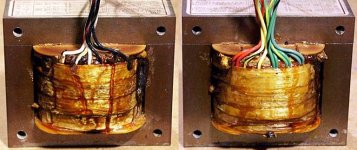
It had a regular EI power transformer most arrogantly labeled 'Counterpoint Advanced Magnetics'. I'm attaching a picture of what became of it...
When the HV transformer was installed separately from the main supplies, the regulation was much improved.
I know - that was the reason I installed it. I still for the life of me cannot figure why there is no regulation on the HV power supply in the original, and even better on the filament supply (though this is not as problematic if well filtered). I mean, these things were NOT cheap - and yet they saw reason to save $1.5 on the circuit.
This must have been an early SA-100. Most I see are REV 3. The drive / buffer tube stage uses a CCS - sort of. I would describe a stock SA-100 as unlistenable + fire hazard. The results of your test are not surprising at all. The SA-220 is an even bigger risk to your fire insurance policy!
-Chris
I can just immagine. I don't know, if it was me, I'd be using a cascode gain stage and an active load follower, or even be adventurous and use an active load gain stage and active load follower, and probably ECL/PCL something tubes with the pentodes triode connected in the follower. You could drive either MOS and BJT with this. It does make the feedback a little bit more difficult to do but not THAT difficult. It may require a DC servo for the tube section, but I think it would be a much better amp.
Attachments
Hi ilimzn,
Yup, those are the original transformers. Not the only one that has gone poof and got stinky. For some reason, Mike likes to install wide band toriods these days. They let in all the AC garbage.
I designed an HV regulator for this amp. If you look, you will find the second stage tube starved. In Mikes cascode output stage the cathode of the bottom tube is tied to the first stage cathode. It's the most non-linear feedback I have ever seen in my life!
Then there is the bias generator for the mosfets. The diodes are run at high current resulting in PCB damage and shorted zeners. That's what turns the fuse covers dark brown. I designed an outboard circuit to fix that too.
The only reason I did this work is that there are many of those in the Toronto area (Canada). After I sold my shop I still had customers hunt me down to see if we could get their amps working "properly".
-Chris
anatech said:Hi ilimzn,
Yup, those are the original transformers. Not the only one that has gone poof and got stinky. For some reason, Mike likes to install wide band toriods these days. They let in all the AC garbage.
Toroids tend to be quite wideband by default, but that's why we have mains filters and shields, as well as properly designed rectifiers and filters on the other side
The one thing I hate when people design power supplies is they forget that ripple currents CAN saturate the core, and once that happens all the myths about low stray fields evaporate...
There is a neat trick to get around this that I used in a very low noise preamp - two toroids stacked one on top of the other wired in series so that their stray fields cancel. It took some time explaining what I wanted to the local toroid winding guys, but they got it eventually. I used the flat type core, and they potted the two into one of their standard cans for me. Worked perfectly!
In Mikes cascode output stage the cathode of the bottom tube is tied to the first stage cathode. It's the most non-linear feedback I have ever seen in my life!
Yes, I think I referred to it in the othe thread. I think this was actually an attempt to get a sort of effectively current mirror - his output is a modified active load follower, it seems. The idea is that the first stage and the active load form a sort of LTP, increase in the first stage current results in the rising of the follower stage voltage, by virtue of increasing the current of the top triode. The rising current also increases the negative bias of the bottom triode through the feedback connection resulting in more effective gain, but using this as a feedback mechanism is dubious, to say the least. And am I the only one that finds the open loop gain of the first stage set unreasonably high? It strikes me that two stages with cathode degeneration and moderate gain and without global feedback would probably be more linear than what he has there, or perhaps just one cascode stage.
Then there is the bias generator for the mosfets. The diodes are run at high current resulting in PCB damage and shorted zeners. That's what turns the fuse covers dark brown. I designed an outboard circuit to fix that too.
Those bias regulators are downright silly. Ohm's law anyone? How about P=V*I? Why drive 36mA through a zener diode when you are only going to use 0.5mA from the regulated power supply??? Never mind he apparently does not seem to be aware of bootstrap current sources. It would have been DEAD easy to bootstrap the bias generator...
BTW that reminds me, someone already swapped the single zeners on mine for two at half the voltage to get better cooling... and the cooked fuse covers were already removed...
And that really is not the proper solution to that problem...
The use of high impedance Vbe multipliers is a no-no in general, running the transistor on long wires with high impedances is an invitation to EMI injection.
Next, current limiting - as in not really. Interesting he has two zeners in antiseries, one of them will never do more than be a regular diode... and, no, they should NOT be the same on the P and N part as their Gm is not the same.
Finally, PCB design: I've seen 8-graders make better designs than that (no, not kidding!). Using a double-sided PCB in face of all the bean-counting 'savings' in that circuit, and then using it for such beginner artwork (the design software didn't have a 45deg track option?!) must be one of the larger ironies in history...
Hi ilimzn,
The gain of the second stage was reduced by starvation. When the current is restored and the plate voltage is sitting around 150V the amp motorboats destructively. Remember the design calls for a +-50V swing and the final grids are connected (almost) directly. When a HV regulator is installed the motorboating problem evaporates. So does a lot of background noise. Then you need to use a combination of feedback and input attenuator to reduce the gain to reasonable levels.
For the bias generator I used a pair of current sources on an outboard PCB. Most the units I see are damaged in this area so the board is needed anyway. These feed a pair of 1W zeners nice and cool. The caps by the zeners are always open so I change them too.
The bias transistor on the leads. Ever see one worked on and the lead breaks off? Boom. The part itself doesn't oscillate, but that's just luck on Mike's part.
The current limiting zeners are only there to prevent exceeding the gate - source breakdown voltage. That's all, no other reason. And yes, the PCB is a huge waste of material. The ground tracks are a joke and it looks like there was at one time an option to float the heaters. That would be a good idea.
-Chris
Counterpoint SA-100 worth modifying???
My brother upgraded to another amp and has a SA-100 to offer me for 400 or so. It has low hours and is in mint shape. I have a pair of Mirage M7si speakers that are power hungry and I'm on a limited budget. I'm consdering purchasing the amp and doing some upgrades, caps, resistors, diodes. Any suggestions, feedback?
My brother upgraded to another amp and has a SA-100 to offer me for 400 or so. It has low hours and is in mint shape. I have a pair of Mirage M7si speakers that are power hungry and I'm on a limited budget. I'm consdering purchasing the amp and doing some upgrades, caps, resistors, diodes. Any suggestions, feedback?
Oscillation
all of the elliot tube stages seem to have an HF ( Tube HF) osillation.
This does not help the sonic qualitied of the amplifier.
I solved it with a SM cap, I will look up the location.
In reality they are great boxes and nice heatsinks.
But not so great amps
I have 4 SA200 / SA220 chassis that I use for my AV amp project for my home theater.
I used a development of a KSA50 design taking the schematic from memory as I could not find one any where! The day after finishing the KSA50 clone project was born!
For your $400 there are other better amps. Go search EBAY.
Or buy a KSA50 bord and go from there.
Brian
Hi Paul,
Sorry, I didn't get a notification.
I think $400 is what you get on Ebay. In my view, those amplifiers are time bombs in stock condition. That and they sound terrible in stock trim. No protection either.
It can look perfect and have serious electronic issues. That has nothing to do with how your brother treated it.
In short, component upgradeswill not help that amp. The basic circuit is very flawed. That includes the output section, and if it blows they can not be repaired easily or cheaply.
I'd walk away from that deal. Pick up a good used amp like a Marantz or Luxman if you can find a good one. There are other brands that are far better than the Counterpoint.
-Chris
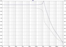
I have seen an HF hash on an SA12 and several SA200, attached is a simulation showing the frequency response of the valve stage.
In all the cases the HF has been around 1.2 Mhz ( about where the siimulation puts it.
The cure I used was to include a 80pf cap to ground from the second stage gate to ground.
Brian
In all the cases the HF has been around 1.2 Mhz ( about where the siimulation puts it.
The cure I used was to include a 80pf cap to ground from the second stage gate to ground.
Brian
Attachments
- Status
- This old topic is closed. If you want to reopen this topic, contact a moderator using the "Report Post" button.
- Home
- Amplifiers
- Solid State
- Counerpoint SA100/200 power amp scheme