The whole idea of the Brio is bad from the start. If a power amplifier if to be driven by an op amp ( TL072 ) it would be better no negative feedback is taken from the output stage to the op amp. This will almost guarantee stability. If the output stage as shown had a gain of 1 it will have remarkably low distortion. It will only give about 7 watts 8 ohms if so.
I have to admit despite my worse fears all the variations of Brio/Texan I built all were better than I imagined. I reduced the output gain to three and two which I felt to be best ( can be 10 ). It's far better than anything similar I built which alas only says how bad the others were.
In this configuration the 3 MHz of TL072 is quite OK. It implies full-power bandwidth of 1Mhz before feedback loop restriction in the Brio set up ( that's fast ). Compare that to most class D designs, it's fast ( class D is complex, outcome is usually a restricted bandwidth ). Even with my gain of 3 option we should get 300 kHz before feedback loop restriction.
Lets say something that never gets said. 90% of people can not hear 20 kHz. If you think you can it might be a sub harmonic. You might hear 14 kHz easily and 16 kHz with the volume raised. However I feel even old people can hear waveform shape when the waveform is complex as music is. Thus an amplifier that has only a single 100 kHz filter of the first order type might sound better to anyone of any age who isn't technically deaf. The output devices and VAS filters cause a more complex order to the filter. I suspect we can hear this. Thus we should make a wide bandwidth amplifier that has one 1st order filter. JLH thought this. JLH avoided the cDom to the VAS solution as that part of the amplifier is already in trouble, why make it worse. The PE Rondo was an improved Texan/Brio.
If you fit NE5532 I would expect a burnout if the behavior of the amplifier wasn't measured into a typical reactive load ( 8R+2uF was typical in the day ). I would not expect it to match a Quad 303 for stability, I would hope it would be OK to work for some minutes. The 5532 gain bandwidth is 3.3 times better than TL072, this will be made of little importance as the feedback loop is restricted. If you say some 30 Mhz output devices could work and retain TL072 that might work. Most repair shops use slow devices as they usually are more stable. Even so, if an external capacitance is added to a fast output device it still might offer a better result as the modern devices are higher gain which makes for lower distortion.
A Paul Kemble web page - PW Texan amplifier and the PE Rondo.
The story I know of the Brio is Roy Gandy boss of Rega requested an amplifier of the simplest design possible to improve. The Texan was used.
The story I know of the Brio is Roy Gandy boss of Rega requested an amplifier of the simplest design possible to improve. The Texan was used.
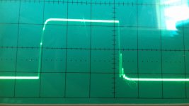
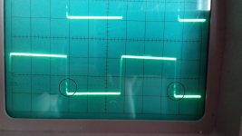
Good news, it's up and running again. I replaced all the transistors in the output section (14) and went with the BD139/140 as drivers. Also replaced a bunch of resistors, some of them had been replaced already (a few with wrong values) and the speaker terminals. I had to repair a certain number of track as well, I think the previous tech went in there with a solder iron for plumbing, it was quite the disaster. Anyway adjusted bias while watching power consumption and monitoring the output for oscillation but everything seems great. Only thing I can see is a little dot (looks like some crossover distortion but I don't have it on the regular sine wave) on the vertical parts of the square wave (that looks perfect except from that).
Square and saw waveforms are the ones to use to reveal the problems....
I don't see anything on a regular sine wave, no matter the frequency or amplitude, it's only there on a square wave (again at any frequency).
...
Well it looks like there is some overshoot on the square waves that causes ringing and that is what we see. It appears on the output of IC3 (but I guess it can also be caused by the negative feedback). When first probing I looked on the wrong IC which led me to see that there is also a little bit of ringing on the output of the tape amp but non on it's input that is taken directly from the output of IC1. could this be a default from those TL072 ?
10 kHz needs at least 190 kHz bandwidth to work. That is about right. That glitch you get I guess is the op amp not closing the loop. Try 5 kHz. 5 kHz is a good test. 1 kHz is about the last sharp square wave a CD can give. 2 kHz should show ripple on a CD player. Triangle waves should work better.
Square wave is F + 1/3F3 + 1/5 F5 + 1/7 F7 + 1/9 F9 + 1/11 F11 + 1/13 F13 + 1/15 F15 + 1/17 F17 +1/19 F19 .... infinity.
Triangle wave is F + 1/9F3 + 1/25F5 + 1/49 F7 + 1/81 F9 + 1/11^2 F11 + 1/13^2 F13 + 1/15^2 F15 + 1/17^2 F17 +1/19^2 F19 .... infinity.
As you might imagine a triangle wave is a filtered square wave, both square and triangle waves have a series of odd harmonics. A French scientist worked this out before the coming of the railways. A triangle wave needs less terms to look OK. A real sawtooth has both odd and even harmonics and was typical of TV scanning waveforms. Much of this was understood by Archimedes. Fourier criticized what many do these days in that the Fourier series looks the same even if a DC component is present. The output capacitor of a JLH solves that. Mains electricity can have DC trends that cause transformer buzz. ESP Audio have a fix for that. If you study mains electricity it's hard to understand where this DC component comes from. I believe it's simply running 3 phase and single phase on the same supply mostly. As all final stage distribution is by transformer no DC quality should come from previous parts of the distribution systems.
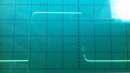
The ringing is there with any frequency on the input as I said before, here are some pictures with a square wave at 5kHz as reference. the first is at the output of IC3, the second as at the speaker terminals, the ringing on the up side isn't there at the output of the amp but it is visible at the ouput of IC3.


Triangle wave looks exactly as it should.


Triangle wave looks exactly as it should.
Sometimes output chokes cause that look. A 10R 3 watt resistor to damp the choke can help. Often the choke is a 16 x 8mm ID wire coil.
If you think about it to include an op amp into the power amp feedback is a crazy idea. I reduced the output amp gain to 3 when I built a clone. The op amp adjusted the actual gain to the same as before. I think it had virtue. 2 could even work. Keep a very careful eye on stability if you do that. I think the 1969 designer used the highest gain he could to get very low distortion and very low output impedance. I feel this was a mistake.
If you think about it to include an op amp into the power amp feedback is a crazy idea. I reduced the output amp gain to 3 when I built a clone. The op amp adjusted the actual gain to the same as before. I think it had virtue. 2 could even work. Keep a very careful eye on stability if you do that. I think the 1969 designer used the highest gain he could to get very low distortion and very low output impedance. I feel this was a mistake.
Try to build one. I found it was very easy to do and didn't need a printed circuit. I didn't use the bias system. Just two diodes and two resistors. I used TIP35/36 which I really liked. I did use NE5532 and MC33078 ( ? ). TLO72 is an excellent choice. I dare say an OPA2604 would be good if possible to find them.
The sound of the Brio is thin. I suspect the transformer is too small. The NAD3020 was a more balanced design.
The sound of the Brio is thin. I suspect the transformer is too small. The NAD3020 was a more balanced design.
- Status
- This old topic is closed. If you want to reopen this topic, contact a moderator using the "Report Post" button.
- Home
- Amplifiers
- Solid State
- Rega Brio (one channel dead)

