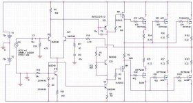
Still having problem with my thermal compensation : I use IRFP240 & 9240 and the VBE multiplier is on the heatsink (MJE340) however the compensation is too high I got distortion when the temperature rise because the quiescent current decreases too much (=0mA!)
I've also try the compensation use by A.Holton in the AV800 : IRF610 and 100Ohm but it seems to be too low the quiescent current rise until 600mA or more
I've read S.Douglas's book has it described some way to change the tempco by adding voltage source and else but it seems quite a hard solution ...
At this point I plan to use a diode in serie with the vbe multiplier (MJE340) and to put only the diode on the heatsink to have small tempco.
Any help or comment is welcome !
David
Hi David !
You can reduce the steepness of your temperature compensation
quite easy.
If you put a series resistor to the emitter of the MJE340 in your
Vbe multiplier.
The value of this resistor depends on the current which is running through MJE340 in your design.
I am now assuming about 10mA steady state current in the VAS:
A good starting point may be a 4.7 Ohm resistor in series to the emitter and then slowly increasing values if the compensation is still
to massive. Please note that you may have to readjust the idle current depending on the additional resistor.
If there is already resistor at the emitter of your
MJE-340- Vbe-multiplier, then you simply could increase this value.
BTW:
Which resistor values do have in series with the
source of your output MOSFETS?
Good luck
Markus
K-amps => It could be a solution, I'll try but I think i'll increase the delay before the current adjusts ...
Markus, Thank you I'll try ! Last time your advices about DC offset were helpfull !! Now my amp is working I just have this quiescent current problem to solve and it will be ok.
The resistor in serie with the mosfet are 0.22 ohm
Thanks
David
Markus, Thank you I'll try ! Last time your advices about DC offset were helpfull !! Now my amp is working I just have this quiescent current problem to solve and it will be ok.
The resistor in serie with the mosfet are 0.22 ohm
Thanks
David
Hi djdamix,
Markus was referring to a series resistance in the emitter of your MJE340. This is exactly what they did in the Counterpoint amps.
When I changed to a bipolar type output the sound became much cleaner, less distorted. Never mind the bias was now easy to control.
-Chris
Markus was referring to a series resistance in the emitter of your MJE340. This is exactly what they did in the Counterpoint amps.
When I changed to a bipolar type output the sound became much cleaner, less distorted. Never mind the bias was now easy to control.
-Chris
I'm working on the thermal compensation & I was wandering what was the recommended quiescent current for AB mosfet amp. It seems that I need about 400mA to make the distortion disapear at 20Khz at about full power (according to my scope)
Does it seems ok ? Can somebody confirm ?
Thanks.
Does it seems ok ? Can somebody confirm ?
Thanks.
Hi David !
I am also curious about the counterpoint amps.
My idea was simply to reduce the impact of the
temperature on the collector current of the Vbe multiplier BJT.
Emitter resistor are the most traditional way to reduce the temperature dependency of a transistor current....
I think your observation of distorsions at high frequencies is
reasonable. I guess your amplifier is the one which you have posted here:
http://www.diyaudio.com/forums/showthread.php?s=&threadid=47479
The open loop gain of this design is not very high and may additionally decrease already below 20 kHz. Your closed loop gain is high.
About 100. So there is not much feedback. You will have to work with
quite some idle current. 400mA do not make me wonder.
Probably you will find output powers which show even higher distorsion than at full load. Did you also try about 10V-20V peak output at 4 Ohms load .... ?
Good luck
Markus
In my amplifier I use CFP output with BJT driving MOSFETs with drain connected to load. Vbe multiplier transistor of the same type as driver is installed on the same small heatsink of a driver transistor (does not matter which one). This way compensation of quiescent current is amazingly good. Maybe small common heatsink for drivers with Vbe mounted there is the best solution. Do not forget that output is CFP.
Try a Vgs multiplier instead or as Chocoholic mentioned,an emitter resistor in the Vbe multiplier.
For the Vgs multiplier you need a MOSFET with reasonably high Gm, so use a higher current one, IRF520, 530 or even 540. Capacitances will not be a problem here as you need to bypass it with a cap anyway (Vgs multipliers are much worse voltage sources than Vbe multipliers due to lower gain).
Since the typical threshold voltage of the IRFP240/9240 is about 3V for some tens of mA of current at 25C, and you have two Vgs to contend with, the Vbe multiplier will need to multiply the typical Vbe by at least 10, so the thermal gradient of Vbe of 2mV/K on the BJT will also be multiplied 10 times, to 20mV/K. which is about 2-3x too much for a VMOS. You will need to experiment with an emitter resistor in the Vbe multiplier. This will depend largely on the current through it, The source resistors, and to a smaller degree on the bias current chosen.
Also, if your supply rails are below 45V or so, you may want to condiser using IRFP240 and IRFP9140 as a complementary pair (both without the N at the end!) - they tend to be more complementary than 240/9240 in nearly everything save the maximum Vds") in your design this might reduce distortion or you may be able to reduce idle current.
in your design this might reduce distortion or you may be able to reduce idle current.
For the Vgs multiplier you need a MOSFET with reasonably high Gm, so use a higher current one, IRF520, 530 or even 540. Capacitances will not be a problem here as you need to bypass it with a cap anyway (Vgs multipliers are much worse voltage sources than Vbe multipliers due to lower gain).
Since the typical threshold voltage of the IRFP240/9240 is about 3V for some tens of mA of current at 25C, and you have two Vgs to contend with, the Vbe multiplier will need to multiply the typical Vbe by at least 10, so the thermal gradient of Vbe of 2mV/K on the BJT will also be multiplied 10 times, to 20mV/K. which is about 2-3x too much for a VMOS. You will need to experiment with an emitter resistor in the Vbe multiplier. This will depend largely on the current through it, The source resistors, and to a smaller degree on the bias current chosen.
Also, if your supply rails are below 45V or so, you may want to condiser using IRFP240 and IRFP9140 as a complementary pair (both without the N at the end!) - they tend to be more complementary than 240/9240 in nearly everything save the maximum Vds
in your design this might reduce distortion or you may be able to reduce idle current.Hi All,
You really do not want to copy a Counterpoint in any way. They are not very good. You also do not want to use IRF mosfets as output devices as in a Counterpoint. The sound quality is very poor. It escapes me how they sold these things to begin with.
A BJT with a degenerated emitter works okay for bias with mosfet outputs. The later SA-100's ran at +- 50 VDC for rails.
I'll say it again, if you copy a Counterpoint, you end up with Counterpoint problems. They are many.
-Chris
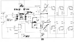
Do you really need M4 & M6 as current gain stage?
If you are using MosFets I would try deal without such a
"darlington" arrangement.
May be you would need to enforce your VAS, but your VAS BJT still have margin. If we assume max. 140V Vce then you can allow 40mA.
My proposal would be to reduces R8 down to 33 Ohms.
But this would require a much higher current setting in you differential input stage.
BTW already now (about 7mA idle current in the VAS ? ) your differential input stage is running at a low idle current. The current into the base of Q21 is not neglectable....
For the input stage I would propose the follwing:
clamp the bases of the differential input to about +/- 15V.
(Two reverse-serial-connected zeners from basis to ground will do it.
==> four 15V- zener diodes)
Additional you can connect 33V zeners in series to the collectors of Q23 und Q24. (==> two further 33V zeners).
If you add the clamping and the collector zeners, then the voltage
load for Q23 and Q24 will be reduced so that you can use BC546 small signal transistors with high gain.....
Just my two cents....
Have fun
Markus
Hi Markus,
I cannot understand your suggestions for using the zeners. Could you post a schematic?
Djdamix,
the ltp appears to have 1mA in the tail (r30 560r), the load resistor (r5 560r) also has about 1mA. This leaves the other half of your LTP (q24) cutoff or very low current.
Try increasing the tail current to about 2mA to balance the LTP. This will increase the first stage gain but you can reduce it by introducing emitter degeneration resistors for q23&24.
anatech said:Hi All,
You really do not want to copy a Counterpoint in any way. They are not very good... The sound quality is very poor. It escapes me how they sold these things to begin with... I'll say it again, if you copy a Counterpoint, you end up with Counterpoint problems. They are many. -Chris
I can only agree with teh above!
SA-100 looks like a high-school science fair project which was backed up by several 10000$ worth (and I am trying to be kind here). The 'Advanced dual output power transformer' is an outright scam, the outputs are connected inside it!!!
As for:
"You also do not want to use IRF mosfets as output devices as in a Counterpoint."
Actually you can use IRFP (not IRF) with fine sound quality IF you know how to pair them. I'll just say this: IRFPXXX and 9XXX are NOT the best pairing (by far) but you can find at least 2 pairs (for rails up to +-45 and up to +-90) that will work great. The Counterpoint does not use the correct ones (though it's a moot point considering they are not made any more), but that's the least of it's problems. The MOSFETs are the least responsible for it's questionable (to say the least) sound...
Hi ilimzn,
Actually ... it's all bad, but, replace the outputs with a bipolar circuit and the sound has improved by a large amount. The IRF fets have an abrupt gate charge change. That is hard to drive.
The entire thing is a bad dream.
I started by trying to eliminate the design errors that made them blow up and sound terrible. One fix lead directly to another until there wasn't much that remained the same. Sounds pretty good now (compared to the original). Still room for improvement but they are on the right track.
I use a stock unit to compare against a modified one against the next step (that's three SA-100's). This way I can keep improvements on track sonicaly and with measurements. That's why I say, "don't even go there" when someone asks about a Counterpoint amp.
-Chris
Hmmm....
I'm planning to use 3-4prs of IRFP240's in an Nch only nested feedback 150W monoblock - as soon as I sort my test eqpt.
Just got to build a low THD wein bridge osc and canyon filter.
They're the best value power around and with a high CMRR FET frontend and nested high PSRR design I'll get my target 0.002% at 20KHz at lower cost than ANY alternative to run on a simple unreg PS with at least 2dB headroom.
Watch this space.
amplifierguru, I agree - I've been using several pairs of IRFPs and they are nearly unbeatable re value for money.
The interesting thing about them is that they are not merely repackaged dies from something like 540, 640 (which I would not use for power amps unless I was making a workhorse so price was an issue and not best performance) etc, but truly independent designs. I was surprised that IR does quite good modeling of these for the linear region, sim results tally with measurements - I consistently get at least 2x lower distortion with IRFPs compared to IRFs in the same circuit (bias has been readjusted of course for minimum distortion on both).
But then I don't pair the IRFPs IR would recomend - i look for as close as possible capacitance matching and transfer characteristics.
The interesting thing about them is that they are not merely repackaged dies from something like 540, 640 (which I would not use for power amps unless I was making a workhorse so price was an issue and not best performance) etc, but truly independent designs. I was surprised that IR does quite good modeling of these for the linear region, sim results tally with measurements - I consistently get at least 2x lower distortion with IRFPs compared to IRFs in the same circuit (bias has been readjusted of course for minimum distortion on both).
But then I don't pair the IRFPs IR would recomend
- i look for as close as possible capacitance matching and transfer characteristics.- Status
- This old topic is closed. If you want to reopen this topic, contact a moderator using the "Report Post" button.
- Home
- Amplifiers
- Solid State
- thermal compensation