Attached is a design for an all-FET cascade line amplifier with gain =5. The left hand side is the actual line amp, and the right hand side is an on-board discrete regulator. One of the channels is left out for clarity. I've just built this thing up and the quiescent bias points are all ok. I'll be taking it in to work tomorrow for a more thorough characterization. PSpice says THD is on the order of 0.005%, with a nice harmonic distribution. At work, I'll take a look at the time and frequency domain response to see if I've set the compensation right, then I'll find out how the thing actually sounds. Using PN4303 instead of PN4393 for the first two common source stages gives me about twice as much distortion, but it may sound better, as the open loop gain is toned down somewhat. I'll have to try it and see.
Attachments
Here is the time domain response of the line amp with a 100kHz square wave input, expanded to show detail of the rising and faling edges. Time scale is 100nsec/div. The faster waveform is the excitation source, and the slower one is the amp response. I had to change compensation cap C4 from 3pF to 12pF to get rid of some overshoot, which also showed up as 3dB worth of peaking in the frequency response. Simulation will only get you so far...
Attachments
Attached is a distortion plot made using an Audio Precision System 2 analyzer, with 1V input (5V out) and 10k load. The distortion is the faint yellow line - next time I'll set the analyser up for something more visible... PSpice predicted 0.016% distortion under tha same conditions, so the real measurement is pretty much on the money compared to the simulation. Simulation did not predict the slight rise in distortion near 20kHz. I'll need to figure out if this is actual distortion or noise. Next will be to measure at 0.1V excitation, where PSpice says the distortion should be around 0.003%. I also want to try using the FFT function in the analyzer to get a harmonic distribution.
Attachments
Hi wrenchone.
You're obviously geared up.
Why the sungle supply design with all the C's partic the feedback electrolytic?
Why not direct couple the 3 stages and DC stabilise the operating point?
Why the complexity of supply, like what else is running on it. You love FETs right/ have a shipload?
You're obviously geared up.
Why the sungle supply design with all the C's partic the feedback electrolytic?
Why not direct couple the 3 stages and DC stabilise the operating point?
Why the complexity of supply, like what else is running on it. You love FETs right/ have a shipload?
Design Constraints:
Must run off +40V single supply already powering current preamp design.
+5X gain (I'm already running a FETWhite source follower and it sounds very nice, but I could use a line amp with a touch more gain).
Must fit the same mounting centers as the current line amp.
JFETs only, preferably N-Channel, and no fancy Japanese devices like the 2SK170, etc. (I have plenty, but they don't make any substantial difference in the distortion anyway, according to the simulation, despite the higher transconductance). Another constraint was to use the components I had on hand, rather than spring for anything expensive and/or exotic.
I don't mind good capacitors - tube circuits use them all the time, why not me... Again, simplicity was the ruling factor. I'm usng Roederstein polypropylenes for input couplers and TRW-35 high current polypropylenes at the output.
I wanted to find out If I could hear the electrolytic. It's polarized with nearly 15V, so this should help the sound. It's a UCC KZE series low ESR cap, which is one notch better than the Panasonic FC or UCC LXZ. I had some misgivings about using it, but it was the only simple way to decouple the gain and quiescent operating current without using a horse-choking film cap.
I've done many, many circuits with dual supplies, symmetric complementary construction, output servo, yada, yada yada, and I want to see how much can be wrung from simple single ended open loop amplifiers or closed loop systems without a whole lot of global feedback. See my thread "open loop follies" for some of the other things I've been doing. My current preamp is all open loop (no global feedback) and sounds wonderful. Now is the time to see if a closed loop lineamp makes any difference in the sound.
I'm also testing to see how close the PSpice simulation can come to predicting actual distortion performance. so far, so good... It didn't do such a good job at predicting the value of compensation cap needed to squelch output overshoot, but the PC board added extra stray capacitance not present in the simulation. I needed approximately 4X the compensation predicted by the simulation.
The power supply circuit is actually relatively simple as things go. I wanted a discrete design, as I am running with a high input voltage, and I have plenty of the necessary parts lying about, including lots of PN4393s and PN4303s. They make nice, simple current sources to improve the performance of the diff amp and the LED voltage reference, but they aren't strictly necessary. Yes, I could have used an IC with the proper buffering for the regulator, but the choice of a discrete circuit was another one of those quirky philosophy-type decisions...
I see wrenchone,
You're in the 'I can do it all with FETs and a single supply' lab - your tubes without the aging and lethal voltages approach.
I just don't like electro's for listening through and it's not as though you can a/b compare! I have designed commercial pre-power combos with only one coupling C (polyprop) in the chain and no servos from 60dB MC phono in to speaker out. It's not an issue then. No C is the best quality C money can buy.
Still why not direct couple the stages? seems like you want each stage to stand alone but then apply feedback. Oh well.
With the constraints I've listed (simple single-ended, all N Channel devices), it's hard to do direct coupling and get decent results. Adding the interstage coupling cap results in the following three benefits:
1) Operating point drift is not coupled and amplified from stage to stage.
2) With the coupling cap, the gain is spread out evenly between the two stages, helping to lessen chances of misbehavior during transients. I can get direct coupling if I use an N-channel input stage folowed by a p-channel stage, but the input stage gain has to be low, so all the gain is concentrated in the second stage, a state of affairs I was trying to avoid. Yes, I realize that I could use a different design topology and get around all of this, but that's not the objective for this exercise.
3) Using the interstage coupling cap allows input and output stages to be biased independently for maximum voltage swing, lessening chances of misbehavior during transients.
I will admit that I could probably get rid of the input coupling cap if I carefully control who talks to my preamp, but the output and interstage caps will stay for this investigation.
Just for grins this afternoon, I did a direct coupled common source cascade simulation with an N-channel input stage and P-channel second stage. As predicted, gain in the first stage needed to be very low to bias the second stage properly. Since the second stage was a J270 (no exotic Japanese FETs here, remember), the second stage gain was pretty low, too, the constraints being realizable drain current for a typical batch of 270s and centering the output drain voltage at 1/2VCC or thereabouts to feed the source follower output stage. The gain was so low that I ended up ditching the feedback network and running totally open loop. Simulated distortion was about 100X that of my original closed loop design, but pretty much all low order. I may actually build this circuit some time down the line to check out how it sounds.
I repeat, I've done totally direct coupled designs of all sorts with decent results. I've done it for over 20 years. That's not the brief here. I'm deliberatly imposing the constraints I've listed to see if the behavior of simple gain structures can be predicted using PSpice, and if the simple amps sound decent. So far, they do.
I have a set of boards I designed and built utilizing a direct coupled folded cascode closed loop topology sitting on my bench waiting to be powered up and put into action. I intend to compare them to my open loop preamp. 3 sets of identical boards have been working 24/7 for 1.5 years in a custom phono preamp box at the master studio of a local college station, where I DJ and help out with engineering. The folded cascode boards will sit on my bench for a good while yet, as feel I haven't adequately explored the possibilities for simpler designs yet and I really like what I'm hearing..
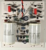
Here's the latest version of the cascade line stage. I'm getting set to plop it into my preamp test bed in place of a current source loaded source follower (described in the thread "open loop follies"). The circuit was reconfigured to remove two coupling caps - one at the input, and one to the gain network. Since I know excatly what's coming after my preamp (the input of the power amp is cap coupled, so there should be no DC impedance to ground to disturb the bias point of the line amp), I feel reasonably sure about hanging the gain network directly at the output of the amp. I probably will include a small resistor iseries with the preamp output to maake sure that cable capacitance doesn't affect the stability of the line amp too badly. More details and some pictures later...
Attachments
Very good circuit, Wrenchone. Congratulations!!
I have found better signal control - audible - with lower value gate bias resistors. You are using 1M; try reducing it to 220K. Seems to sound better with tubes, at least.
Like the use of low feedback (I'm assuming 26dB, correct?) jfet amplification. Your figures bear out very low distortion. Have you tried it with one gain stage and only 9.5dB of feedback? Distortion will be higher, but it should sound better again.....
Cheers,
Hugh
I love FETs - especially monothically matched ones as the spreads are onerous to design with. But they result 'generally' (qualifier) in considerably lower impedance to the supply - throwing the onus for performance on the power supply. Hence my comments re supply quality. But it's not a power amp so less of an issue.
I would never use them un-cascoded in a power amp front end.
Cheers,
Greg
I would never use them un-cascoded in a power amp front end.
Cheers,
Greg
The power supply is a shunt regulator this time around - it does just fine. I deliberately shied away from using a TL431, though I could have tried one with a cascode transistor to allow it to withstand the 40V supply.
This lineamp is the first of a series of low-medium feedback circuits. The second is a JFET version of the Aikido tube lineamp, at least in its basic topology, consisting of a common source amp with current source loading driving a follower. Since it is an inverting amplifier, the feedback network structure is different, and it will probably require me to change over to a lower resistance volume pot when I try it out. The third uses a common source amp with a current mirror to redirect the drain current, driving a source fiollower. Circuits will be posted when get close to trying each new board out.
I'l be trying the circuit I just posted fairly soon, as soon as I'm a little more used to the new RIAA preamp I recently placed in my test bed (see my thread on a JFET SRPP RIAA preamp).
As for the suggestion on the second stage JFET resistor - I may try that, as it only pushes up the LF breakpoint to about 1.7Hz, which would still be acceptable.
To amplifierguru - I still have the original lineamp circuit with all the coupling capacitors, and I intend to slip it into my test bed at some point to see if it makes an audible change in the sound.
It's fascinating - every change I've made so far in my test bed has made some sort of audible difference. The first test bed setup with a modified Pacific RIAA amp and a source follower line stage was miles better than the 70's vintage Nikko preamp it replaced. The new SRPP RIAA preamp has a different sonic palette than the Pacific. I like what it does for harp and vibes. The new lineamp may change the sonic palette yet again.
- Status
- This old topic is closed. If you want to reopen this topic, contact a moderator using the "Report Post" button.
- Home
- Amplifiers
- Solid State
- JFET Cascade Line Amp